Back-up camera
Back-up camera
When manoeuvring with the vehicle, the back-up camera provides a possibility to show the perspective to the rear on the display. Depending on the current settings, a number of assistance graphics can be overlaid on the video image. In addition, an automatic speed-dependent camera pan can be activated. Depending on the setting in the iDrive menu, the camera image is shown as full screen or in the main window (2/3 display).
The back-up camera provides support for manoeuvring and hitching trailers. For vehicles with an original BMW trailer coupling, the back-up camera has a zoom mode.
The back-up camera does not replace the direct appraisal of the traffic situation by the driver!
Brief description of components
The following components are described for the back-up camera:
RFK: Back-up camera
The back-up camera is installed in the luggage compartment lid. The camera and control module are fitted in one housing. The image distorted by the curvature of the lens is compensated for by the software in the control module.
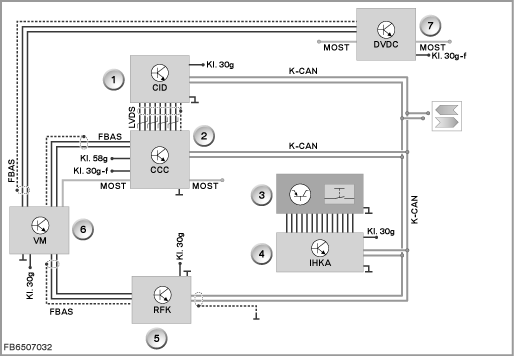
Depending on the vehicle equipment, the signals of the back-up camera are transferred directly or indirectly (via the video module or video switch or video changeover switch) to the head unit.
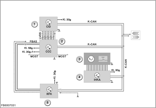
Index |
Explanation |
Index |
Explanation |
|---|---|---|---|
1 |
Central Information Display (CID) |
2 |
Head unit (CCC: Car Communication Computer) |
3 |
PDC button in the centre console switch cluster |
4 |
Integrated automatic heating and air conditioning system (IHKA) |
5 |
Back-up camera (RFK) |
|
|
CVBS |
Composite Video Burst Synch signal or RGB signals (depending on the national version) |
K CAN |
Body CAN |
Terminal 30 |
Terminal 30 |
Terminal 30g |
Terminal 30 switched |
Terminal 30g-f |
Terminal 30g-f |
Terminal 58g |
Terminal 58g, locating light |
LVDS |
Data wire (Low Voltage Differential Signalling) |
MOST |
Fiber Optics |
PDC button
The PDC button is used to manually activate and deactivate not only the parking aid (PDC: Park Distance Control) but also the back-up camera (forced connection optional extra 3AG ”back-up camera” with optional extra 508 ”Park Distance Control (PDC)”). The IHKA control module reads in the status of the button. The IHKA control module sends the status as a message on the K-CAN. The message is received by the control module of the back-up camera.
VM: Video module
Depending on the vehicle equipment, the image of the back-up camera is not transferred to the head unit but rather to the video module.
The video module consists of a TV receiver with videotext function and antenna diversity as well as an internal changeover for the video sources.
If required, the internal selector switch in the video module switches the Composite Video Burst Synch signals (CVBS) or RGB signal (the signals depend on the national version) either from the TV receiver or the back-up camera through to the head unit.
The video module means that the back-up camera can be offered in conjunction with the optional extra ”TV function”.
Index |
Explanation |
Index |
Explanation |
|---|---|---|---|
1 |
Central Information Display (CID) |
2 |
Head unit (CCC: Car Communication Computer) |
3 |
PDC button in the centre console switch cluster |
4 |
Integrated automatic heating and air conditioning system (IHKA) |
5 |
Back-up camera (RFK) |
6 |
Video module (VM) |
7 |
DVD changer (DVDC) |
|
|
CVBS |
Composite Video Burst Synch signal or RGB signals (depending on the national version) |
K CAN |
Body CAN |
Terminal 30 |
Terminal 30 |
Terminal 30g |
Terminal 30 switched |
Terminal 30g-f |
Terminal 30g-f |
Terminal 58g |
Terminal 58g, locating light |
LVDS |
Data wire (Low Voltage Differential Signalling) |
MOST |
Fiber Optics |
VSW: Video switch
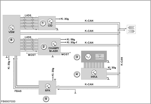
Depending on the vehicle equipment, the image from the back-up camera is not transferred to the head unit, rather to the video switch.
If the head unit is unable to process video signals, the digital video switch converts the Composite Video Burst Synch signal (CVBS) of the back-up camera into an LVDS signal. Depending on requirements, either the camera image or the image of the head unit is transferred to the Central Information Display.
Index |
Explanation |
Index |
Explanation |
|---|---|---|---|
1 |
Central Information Display (CID) |
2 |
Head unit (CHAMP: multimedia platform or M-ASK: Multi-audio system controller) |
3 |
PDC button in the centre console switch cluster |
4 |
Integrated automatic heating and air conditioning system (IHKA) |
5 |
Back-up camera (RFK) |
6 |
Video switch (VSW) |
CVBS |
Composite Video Burst Synch signal or RGB signals (depending on the national version) |
K CAN |
Body CAN |
Terminal 30 |
Terminal 30 |
Terminal 30g |
Terminal 30 switched |
Terminal 30g-f |
Terminal 30g-f |
Terminal 58g |
Terminal 58g, locating light |
LVDS |
Data wire (Low Voltage Differential Signalling) |
MOST |
Fiber Optics |
Video changeover switch
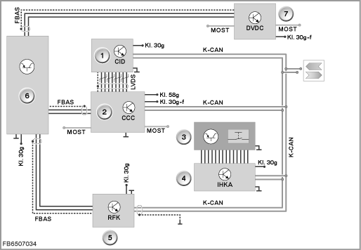
The automatic video changeover switch is a hardware solution to toggle between two video sources in the vehicle.
Video sources in the vehicle:
- Back-up camera
- DVD changer
The back-up camera is the master controller. The DVD changer is the slave.
If the video signals of the two video sources arrive at the video changeover switch simultaneously, only the video signal from the back-up camera is switched through to the output of the video changeover switch.
If the video signal from the back-up camera is not present, the video signal from the DVD changer is switched through.
The video changeover switch means that the back-up camera can be offered in conjunction with the optional extra ”DVD changer, 6-way” even without the optional extra ”TV function”.
Index |
Explanation |
Index |
Explanation |
|---|---|---|---|
1 |
Central Information Display (CID) |
2 |
Head unit (CCC: Car Communication Computer) |
3 |
PDC button in the centre console switch cluster |
4 |
Integrated automatic heating and air conditioning system (IHKA) |
5 |
Back-up camera (RFK) |
6 |
Video changeover switch |
7 |
DVD changer (DVDC) |
|
|
CVBS |
Composite Video Burst Synch signal or RGB signals (depending on the national version) |
K CAN |
Body CAN |
Terminal 30 |
Terminal 30 |
Terminal 30g |
Terminal 30 switched |
Terminal 30g-f |
Terminal 30g-f |
Terminal 58g |
Terminal 58g, locating light |
LVDS |
Data wire (Low Voltage Differential Signalling) |
MOST |
Fiber Optics |
CD: Control Display
The image of the back-up camera is shown on the display. Depending on the setting, it appears as full screen or only in the left-hand area of the CID.
System functions
The following system functions are described for the back-up camera:
- Voltage supply
- Personalization
Voltage supply
The back-up camera is supplied via terminal 30g. The fuse is located in the rear distribution box.
Personalization
The following settings can be personalized:
- Display format, full screen on/off
- Maximum curve radii for the turning circle on/off
- Driving lane on/off
- Distance graphic on/off
- Camera pan on/off
The following specific additional functions are described for the back-up camera:
- Assistance graphics
- Lens heating
Assistance graphics
Various assistance graphics in the form of overlays (graphics and text) can be overlaid in the image of the camera. The assistance graphics can be enabled or disabled in the menu of the back-up camera.
- Maximum curve radii for the turning circle:
These radii illustrate the maximum turning circle in the camera image. - Marking lines for the driving lane:
The driving lane depends on the steering-wheel angle. The marking lines show the predicted driving lane of the vehicle and thus the space required for manoeuvring. - Distance graphic:
When the parking aid (PDC: Park Distance Control) detects an obstacle, a distance graphic appears in the real image. The graphic changes colour depending on the gap to the obstacle. The colours run from red to green. - Virtual camera pan:
The camera pan can be used to change the vertical angle of view of the camera. The camera image pans virtually without the camera moving mechanically.
Depending on the driving speed, different angles of view are shown in the vertical direction and as full screen.
In the case of slow reversing (below 5 km/h), the lower angle of view (from the bumper to the horizontal) is displayed to enable recognition of a much detail as possible behind the vehicle.
With faster reversing (above 5 km/h), the angle of view changes upwards (that is: as of 1 metre ground clearance from the bumper to at least 10° above the horizontal). - Zoom to trailer coupling:
The zoom trailer coupling is a zoomed display of the rear end. Overlaid distance graphics (interactive artificial lines as well as marking lines for the gap depending on the steering angle) enable convenient hitching of a trailer.
Lens heating
The lens of the back-up camera is heated. The heating element is actuated with a pulse-modulated signal (PWM signal) by the control module of the rear view camera. A defective heating element causes a fault memory entry.
Notes for Service department
General information
The back-up camera switches the image output off when it is not active.
Diagnosis instructions
- Depending on the coding, the picture signal is transferred by a Composite Video Burst Synch signal (CVBS) or an RGB signal in the vehicle.
- A soiled lens can lead to a poor representation. In extreme cases, the camera can no longer evaluate pictures. This means a soiled lens can lead to a system failure. To prevent an incorrect diagnosis, the optical elements of the camera must be cleaned.
- After replacement of the camera, it must be calibrated!
Conditions for switching on and off
The back-up camera is switched on under the following conditions:
- Pressing the PDC button (as of terminal 15 On)
- Reverse gear engaged (back-up camera switched on automatically)
The back-up camera is switched off under the following conditions:
- Pressing the PDC button
- After a distance driven of approx. 50 metres (forwards)
- After exceeding a speed of approx. 20 km/h
- Via iDrive (can also be disabled permanently)
No liability can be accepted for printing or other faults. Subject to changes of a technical nature