M twin-clutch transmission
M twin-clutch transmission
In the BMW M3 (development series: E9x M3), a twin-clutch transmission will be deployed worldwide as of 03/2008. The M twin-clutch transmission (M DKG) has 7 gears and it enables gearshifts without tractive power interruptions.
On the M twin-clutch transmission, clutch operation and gear changes are automated. An electrohydraulic control system handles clutch operation and gearshifts. The clutch pedal is no longer required.
The M twin-clutch transmission combines 2 partial transmissions with 2 clutches (designed as wet clutches). One partial transmission with clutch is responsible for the even-numbered transmission stages (2, 4, 6). The other partial transmission with clutch is responsible for the odd-numbered transmission stages (1, 3, 5, 7) as well as for reverse gear.
While the vehicle is being driven, one of the two clutches is closed. With each gear change, one clutch opens parallel to the other clutch closing. This achieves jolt-free and rapid gear changes without tractive power interruptions.
The main reason for the application of two clutches enabling very fast gear changes without tractive power interruption is that the Electronic Transmission Control selects the next gear with the ideal gear ratio for the relevant engine speed and driving speed in advance and is ready with this gear.
Example: The vehicle is accelerating in 3rd gear. In the partial transmission with the even-numbered transmission stages, the gear required to continue the acceleration, in this case 4th gear, is already engaged. If the clutch responsible for 4th gear now closes, the clutch for the 3rd gear opens simultaneously. This shift operation takes only a few milliseconds.
The M twin-clutch transmission can be used manually in the sequential mode ”S” and in the automated drive mode ”D”.
The gear selector switch is attached to the bus. The shift pulses are transferred electrically to the DKG control module. With this gearshift method (”shift-by-wire”) there is no mechanical linkage between the gear selector lever or gearshift paddles and the transmission.
”Drivelogic” provides a total of 11 drive programs. These are used to adapt the shift characteristics of the M twin-clutch transmission to the desired driving style.
The M twin-clutch transmission is configured for a torque of up to 520 Newton metres and engine speeds of up to 9000 rpm.
The M twin-clutch transmission weighs 89 kg (including double-mass flywheel).
Brief description of components
The M twin-clutch transmission essentially consists of the following components:
Arrangement of the components in the M twin-clutch transmission
- M twin-clutch transmission, view from the left
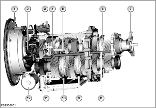
Index |
Explanation |
Index |
Explanation |
|---|---|---|---|
1 |
Housing of the twin clutch |
2 |
Oil pump |
3 |
Transmission connector |
4 |
Selector rod 4/6 with shift fork |
5 |
Gear set |
6 |
Selector rod 5/7 with shift fork |
7 |
Output flange |
8 |
Oil line for the direct lubrication |
9 |
Selector rod 1/3 with shift fork |
10 |
Selector rod 2/R with shift fork |
11 |
Oil filter in the intake line |
12 |
Oil filter in the oil pressure line |
- M twin-clutch transmission, view from rear right
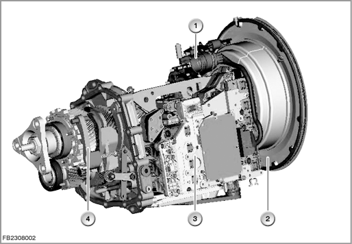
Index |
Explanation |
Index |
Explanation |
|---|---|---|---|
1 |
Transmission connector |
2 |
Housing of the twin clutch |
3 |
Mechatronics module |
4 |
Parking lock pawl (part of the parking lock) |
Schematic structure with sensors
The signals from the sensors are transferred directly to the DKG control module. In addition, the oil sump temperature is calculated in the DKG control module using a complex temperature model. For the plausibility check, the calculated temperature is checked against the
temperature registered by the temperature sensors in the DKG control module as well as the sensor for cooling oil temperature in the twin clutch.
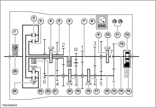
Index |
Explanation |
Index |
Explanation |
|---|---|---|---|
1 |
Combined sensor for twin-clutch transmission (sensor for transmission input speed and sensor for cooling oil temperature on the twin clutch) |
2 |
Clutch of the partial transmission 1, directly connected to the inner input shaft 1 |
3 |
Clutch of the partial transmission 2, directly connected to the inner input shaft 2 |
4 |
Gearshift travel sensor, picks up the current end position of the selector shaft (4th or 6th gear) |
5 |
Gearshift sleeve (4th or 6th gear) |
6 |
Input engine speed sensor for partial transmission 1 with direction of rotation detection for the inner input shaft 1 |
7 |
Inner input shaft 1 of the partial transmission 1 |
8 |
DKG control module (component of the mechatronics module) |
9 |
Gearshift sleeve (5th or 7th gear) |
10 |
Gearshift travel sensor, picks up the current end position of the selector shaft (5th or 7th gear) |
11 |
Temperature sensors in the DKG control module |
12 |
Gear wheels always engaged |
13 |
Parking lock |
14 |
Sensor for the parking lock (redundant) |
15 |
Transmission output shaft |
16 |
Auxiliary shaft |
17 |
Gearshift sleeve (1st or 3rd gear) |
18 |
Gearshift travel sensor, picks up the current end position of the selector shaft (1st or 3rd gear) |
19 |
Gearshift sleeve (2nd or reverse gear) |
20 |
Gearshift travel sensor, picks up the current end position of the selector shaft (2nd or reverse gear) |
21 |
Inner input shaft 2 of the partial transmission 2 |
22 |
Input engine speed sensor for partial transmission 2 for the inner input shaft 2 |
23 |
Oil pressure sensor for clutch 2 |
24 |
Oil pressure sensor for clutch 1 |
25 |
Transmission input shaft |
|
|
The two sensors that measure the transmission input speed and cooling oil temperature on the twin clutch are grouped in the combined sensor for the twin-clutch transmission.
GWS: Gear selector switch
The gear selector switch is configured as a control module in its own right. The M twin-clutch transmission is electronically activated via the gear selector switch. The gear selector switch is supplied with voltage via terminal 30g.
The gear selector switch consists of the control electronics circuit and the gear selector lever. 14 Hall sensors for non-contacting detection of the gear lever position are integrated in the control electronics circuit. The gear lever position is sent across the PT-CAN and redundantly across the LIN bus to the DKG control module (also referred to as: EGS control module). This means that data are sent to the DKG control module even if one of the two transmission lines fails.
The moved program switch for ”Drivelogic” is connected directly to the control electronics circuit of the gear selector switch.
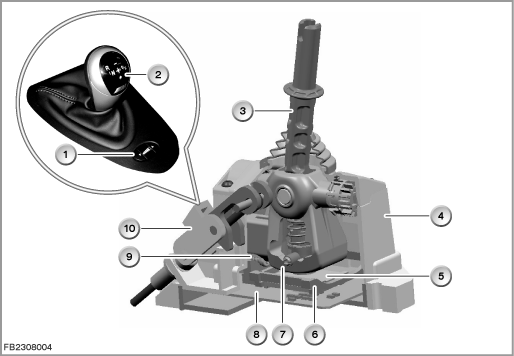
Index |
Explanation |
Index |
Explanation |
|---|---|---|---|
1 |
Program switch for ”Drivelogic” |
2 |
Function indicator with gear diagram in the gear selector lever |
3 |
Gear selector lever with spring for the interlock |
4 |
Gear selector switch |
5 |
Lateral slider with permanent magnet on the bottom (to detect the gear lever position via the Hall sensors), directly connected with the gear selector lever and guided in the longitudinal slider |
6 |
Longitudinal slider, guided in the housing of the gear selector switch |
7 |
Haptics for shifting in direction of travel |
8 |
Control electronics circuit with Hall sensors |
9 |
Haptics for shifting across direction of travel |
10 |
Parking lock (not component of the gear selector switch) |
The function indicator is shown in the gear selector lever. The function indicator is shown as a shift diagram. The drive position engaged is displayed in the function indicator regardless of the gear lever position.
The engaged drive position is only shown in the shift diagram when the Electronic Transmission Control (DKG control module) has implemented the driver's demand and the gear selector switch has confirmed this state via a message across the bus. The function indicator is active as long as the bus communication on the PT-CAN or LIN bus is active.
The gear selector lever is mono-stable, i.e. it always returns to its initial position.
The change to gear lever position ”R” is bi-stable, i.e. the gear selector lever remains in the selected gear lever position. A shift from the gear lever position ”R” into the automated drive mode ”D” or the sequential mode ”S” can only be carried out manually.
Program switch for ”Drivelogic”
”Drivelogic” provides a various drive programs. These are can be used to adapt the shift characteristics of the M twin-clutch transmission to the desired individual driving style.
- 5 drive programs in the automated drive mode ”D”
- 6 drive programs in the sequential mode ”S”
(drive program 6 only sequential with DSC switched off or with Launch Control.)
The signals of the program switch for ”Drivelogic” are transferred by hard-wired lines to the control electronics circuit of the gear selector switch.
Gearshift paddles on steering wheel
In addition to conventional gear selection using the gear selector lever, the gears can also be selected using the 2 gearshift paddles on the steering wheel.
- Upshift: pull the right gearshift paddle
- Downshift: pull the left gearshift paddle
Mechatronics module
The M twin-clutch transmission is controlled by the mechatronics module. The mechatronics module is a combination of a hydraulic unit and electronic module.
The mechatronics module is installed in the M twin-clutch transmission.
The hydraulic unit is the hydraulic part of the transmission control. The hydraulic unit contains, for example, the electronic pressure control valves and shifting travel valves for control of the hydraulic shift cylinders.
The electronic pressure control valves convert an electric current specified by the DKG control module into a proportional hydraulic pressure. The electronic pressure control valves operate the valves that belong to the shift elements.
The 4 selector rods are shifted in a longitudinal direction by the hydraulic shift cylinders in the hydraulic unit.
The electronic module contains the DKG control module, the sensors as well as the transmission-internal electrical connections.
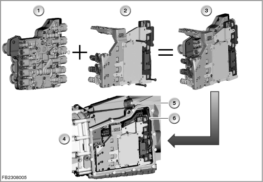
Index |
Explanation |
Index |
Explanation |
|---|---|---|---|
1 |
Hydraulic unit |
2 |
Electronic module |
3 |
Mechatronics module |
4 |
Installation location of the mechatronics module |
5 |
Transmission connector |
6 |
Internal transmission wiring harness |
Oil pump
The oil pump in the M twin-clutch transmission builds up the hydraulic pressure required with the engine running. The oil pump is geared to the transmission input shaft.
The hydraulic pressure is determined depending on the load and function by an activated control valve. A pressure limiting valve in the oil pump prevents excessive hydraulic pressure in the hydraulic system.
Normally, the system pressure lies between 5 and 20 bar. In exceptional cases, the system pressure can be increased to up to 30 bar. The maximum shift pressure to shift the selector rods in the longitudinal axis can be equal to the system pressure.
The shift pressure for the twin clutch or for both clutches is limited to 18 bar.
The following control modules and components are involved in the function of the M twin-clutch transmission (in alphabetical order):
Brake-light switch
The signal of the brake-light switch is processed in the Digital Motor Electronics (DME). The Digital Motor Electronics send the signals as a CAN message on the CAN bus.
The signal of the brake-light switch is used for the following operations:
- start enable
- detection of braking
- adaptive transmission control
- driving off on inclines
CAS: Car Access System
The Car Access System only enables the starter motor when the enable signal comes from the DKG control module.
For start enable, the following conditions must be met:
- The automatic parking lock must be engaged.
- The DKG control module enables the start when the brake pedal is pressed.
The Car Access System also delivers input signals with regard to the terminal voltage, e.g. terminal 15 wake-up. Switching on terminal 15 activates (wakens) the control modules on the PT-CAN via the wake-up line (terminal 15 wake-up).
CID: Central Information Display
Detailed information about the Check Control messages in the instrument cluster is displayed on the Central Information Display. The instrument cluster controls these messages on the K-CAN (body CAN). In addition to the visual display, the Check Control also alerts the driver with acoustic signals.
DSC: Dynamic Stability Control
The Dynamic Stability Control optimizes driving stability when driving off and accelerating and also optimizes traction. The Dynamic Stability Control corrects driving states such as oversteer and untersteer within physical boundaries. As part of this process, dynamic driving signals (e.g. wheel rotation speed, lateral acceleration) are sent to the DSC control module. The Dynamic Stability Control sends the processed signals for cornering and acceleration detection to the DKG control module.
FPM: Accelerator pedal module
The signal of the accelerator pedal module (driver's demand) is required for permanent checking of each driving status (evaluation via DME).
FRM: Footwell module
Based on messages from the DKG control module to the footwell module, the footwell module switches the backup lamp on or off, as the case may be. The footwell module supplies, among other things, the locating lights of the program switch for ”Drivelogic”.
The footwell module also evaluates the status of the Hall sensors in the door contacts. The status is sent as a message on the CAN bus and tune in by the DKG control module. If the driver's door is opened with the engine running, visual as well as acoustic signals draw attention to the position of the transmission.
JBE: junction box electronics
Junction Box electronics is the data interface (= gateway) between the K-CAN and PT-CAN (K-CAN stands for ”body CAN”; PT-CAN stands for ”Powertrain CAN”).
The junction box consists of the junction box electronics and the distribution box. The distribution box supplies among other things the gear selector switch and the DKG control module.
The D-CAN (diagnosis-on CAN) is connected to the junction box electronics.
KOMBI: Instrument cluster
The selected drive positions and drive programs are displayed in the instrument cluster by means of a CAN message from the DKG control module.
The brightness of the function indicator in the selector lever knob is adapted to the lighting conditions or surrounding brightness in each case. To achieve this, the signals of the photo-transistors in the instrument cluster are evaluated.
The brightness value calculated in the instrument cluster is sent across the CAN bus to the gear selector switch.
Dimming can be set individually via a menu in the instrument cluster.
With the vehicle lighting switched on, these individual specifications and the photo-transistor are used to control dimming.
With the vehicle lighting switched off, dimming is only controlled by the photo-transistor.
System functions
The following system functions of the M twin-clutch transmission are described:
- Functional networking
- Transmission oil cooling
- Cooling of the twin clutch
- Engine start
- Overlap control
- Drivelogic
- Driving in gear lever position ”D” (automated drive mode)
- Launch Control (acceleration assistant)
- Slip detection
- Driving off on inclines
- Low Speed Assistant
- Vehicle at a standstill
- Automatic parking lock
- Emergency program
Functional networking
A complex composite system with distributed functions in other control modules is necessary for implementation of the transmission functions. The DKG control module is connected across data bus with these other control modules.
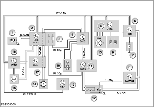
Index |
Explanation |
Index |
Explanation |
|---|---|---|---|
1 |
Additional coolant pump |
2 |
Junction box electronics (JBE) in the junction box |
3 |
Power distributor in junction box |
4 |
DKG control module |
5 |
Digital Motor Electronics (DME) |
6 |
Footwell module (FRM) |
7 |
Driver's side door contact |
8 |
Instrument cluster (KOMBI) |
9 |
Brake-light switch |
10 |
Accelerator pedal module |
11 |
Gear selector switch (GWS) |
12 |
Program switch for ”Drivelogic” |
13 |
Car Access System (CAS) |
14 |
Gearshift paddles on steering wheel |
15 |
DSC sensor |
16 |
DSC (Dynamic Stability Control) |
17 |
Steering column switch cluster (SZL) |
18 |
Electromagnet for the parking lock |
D-CAN |
Diagnosis-on CAN |
F-CAN |
Chassis CAN |
K CAN |
Body CAN |
Kl. 15 WUP |
Wake-up line (terminal 15 wake up) |
Kl. 30g |
Terminal 30 switched |
Kl. 58g |
Terminal 58g, locating lamp |
PT-CAN |
Powertrain CAN |
|
|
Transmission oil cooling
For transmission oil cooling, the hydraulic fluid is always fed via the oil-coolant heat exchanger.
As of a certain transmission oil temperature, the transmission oil thermostat ensures that the hydraulic fluid is additionally fed via the oil-air heat exchanger.
The oil-coolant heat exchanger is integrated on coolant side in the heater circuit of the vehicle.
The coolant for the heat exchanger flows out of the extraction point on the coolant pipe between the cylinder banks directly into the oil-coolant heat exchanger.
After passing through the oil-coolant heat exchanger, the coolant flows via the electric auxiliary coolant pump into the heat exchanger for the heating system.
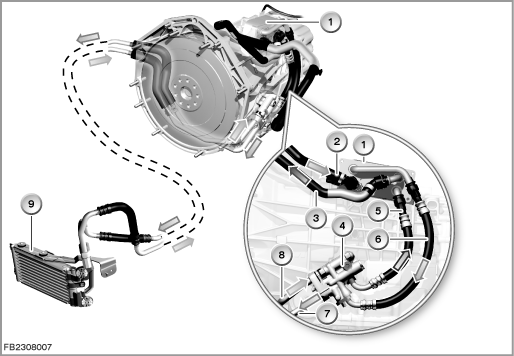
Index |
Explanation |
Index |
Explanation |
|---|---|---|---|
1 |
Oil-coolant heat exchanger |
2 |
Feed (coolant) from heater circuit of the vehicle to the oil-coolant heat exchanger |
3 |
Return flow (coolant) from oil-coolant heat exchanger to the auxiliary coolant pump |
4 |
Transmission oil thermostat |
5 |
Oil return from transmission oil thermostat |
6 |
Oil supply from oil-coolant heat exchanger to the transmission oil thermostat |
7 |
Oil supply to the oil-air heat exchanger |
8 |
Oil return from oil-air heat exchanger |
9 |
Oil-air heat exchanger |
|
|
The transmission oil thermostat opens or closes depending on the temperature.
- Transmission oil temperature below approx. 95 °C:
The transmission oil thermostat is closed.
The short circuit is open. This means the supplied hydraulic fluid is not fed via the oil-air heat exchanger but rather directly via the open short circuit into the return flow.
If required, the electric auxiliary coolant pump is requested via the DKG control module. To achieve this, the DKG control module a message across the PT-CAN. The junction box electronics receive the message and switch the auxiliary coolant pump on.
Normally, the purpose of the electric auxiliary coolant pump is to ensure the necessary coolant flow volume in the heater circuit at low engine speeds. - Transmission oil temperature above approx. 95 °C:
The transmission oil thermostat is opened.
The short circuit is closed. This means the hydraulic fluid is fed via the oil-air heat exchanger.
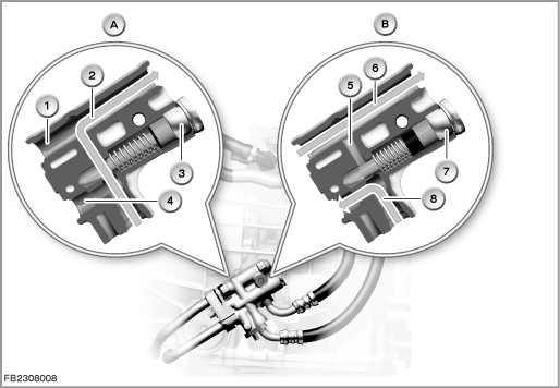
Index |
Explanation |
Index |
Explanation |
|---|---|---|---|
A |
Transmission oil thermostat closed |
B |
Transmission oil thermostat opened |
1 |
Oil return line from oil-air heat exchanger (oil flow only with short circuit closed) |
2 |
Oil return from oil-coolant heat exchanger (short circuit open) If the short circuit is open, for physical reasons the hydraulic fluid does not flow via the oil-air heat exchanger |
3 |
Thermostat (short circuit open) |
4 |
Supply to oil-air heat exchanger (oil flow only with short circuit closed) |
5 |
Short circuit |
6 |
Return flow from oil-air heat exchanger (short circuit closed) |
7 |
Thermostat (short circuit closed) |
8 |
Oil supply from oil-coolant heat exchanger to oil-air heat exchanger (short circuit closed) |
Note! Reduction in torque and engine-speed limitation with excessive transmission oil temperature.
If the transmission oil temperature rises above a certain limit value, the engine torque is reduced and, if required, the engine speed is limited. A Check Control message is displayed (yellow Check Control symbol). The shift program is changed to reduce the transmission oil temperature.
If the transmission fluid in the oil sump or in the twin clutch reaches a non-permitted excessive limit value, the engine torque is greatly reduced. A Check Control message is displayed (red Check Control symbol). The engaged gear remains engaged until the vehicle is at a standstill. With the vehicle at a standstill, the parking lock is engaged.
It is only possible to continue driving once the transmission fluid has cooled.
Cooling of the twin clutch
To cool the twin clutch, hydraulic fluid from the oil sump is sprayed onto the twin clutch. The sensor for the cooling oil temperature on the twin clutch is hit by the jet spray of the cooling oil. The temperature signal is sent to the DKG control module.
The heat management determines the current cooling requirement and regulates the cooling system accordingly. To achieve this, the DKG control module activates a solenoid valve.
The solenoid valve has 3 positions:
- Position with minimum flow to twin clutch (no current)
- Opened position
- Closed position
If the oil sump temperature is implausible in relation to the temperature of the cooling oil in the twin clutch, a Check Control message is displayed.
Engine start
Independently of the drive position and gear in which the engine is turned off, the engine can only be started when the brake is operated. On engine start, the parking lock is always engaged.
If the engine is started in the gear lever position ”R”, the symbol for the mono-stable position flashes in the function indicator in the gear selector lever.
On unlocking the vehicle, the DKG control module is wakened by the Car Access System (CAS).
Overlap control
When a gearshift is triggered in the sequential mode ”S” or in the automated drive mode ”D”, the DKG control module activates the corresponding solenoid valves. Simultaneously, the DKG control module sends a message to the DME control module indicating that a gearshift operation is being initiated. The engine torque is reduced. During the gearshift, the engine speed is raised if required to make clutch engagement faster and more comfortable.
The DKG control module activates the twin clutch, the solenoid valves and the hydraulic shift cylinders. The shift cylinders execute the longitudinal movement (forward or backward movement) of the corresponding selector rods. The desired gear is engaged.
The overlap control ensures optimized shift characteristics as follows: in the overlap control, both clutches are used simultaneously. In the engaged clutch the pressure is reduced and simultaneously pressure is built up in the clutch to be engaged. The pressure decrease or pressure build-up is maintained until a synchronized speed is reached. Then, the hydraulic pressure for the clutch to be engaged can be built up in full.
After the shift operation, the current to the solenoid valve is switched off.
The entire gearshift operation runs depending on the accelerator pedal position, engine speed, driving speed and other control variables (e.g. engine oil temperature, selected drive program).
Gearshifts that would lead to non-permitted high or low engine speeds are not executed.
Drivelogic
”Drivelogic” provides a total of 11 different drive programs.
- In the automated drive mode ”D” (automatic operation), there is a choice of 5 drive programs (from ”relaxed” to ”sports”).
In drive program 1, for example, 2nd gear is selected for driving off. The clutch works particularly sensitively. This makes driving off easier on winter roads. - In the sequential mode ”S” (manual operation), there is a choice of 6 drive programs (from ”balanced dynamic” to ”very sporty”).
Drive program 6 is only possible when DSC is switched off and it is a precondition for Launch Control (acceleration assistant).
As a general principle, the drive programs differ with regard to the preselected shifting time: the higher the drive program, engine speed and load, the shorter the shifting time.
Driving in gear lever position ”D” (automated drive mode)
- Constant driving
The DKG control module registers continuous changes to the accelerator pedal position (accelerate and decelerate). The DKG control module the continuous change between neighbouring gears that this causes (back and forth, e.g. on a journey on the motorway with continuously changing speed). - Suppressing upshifts
The DKG control module uses the accelerator pedal position to detect rapid closure of the throttle, e.g. before braking.
The DKG control module suppresses the upshift. This means that the engine braking effect is retained and it supports braking. - Manual intervention in the automated drive mode ”D”
If the gear selector lever is operated towards upshift or downshift or if the shift paddles are operated in the automated drive mode ”D”, there is an automatic switch into the sequential mode ”S”.
The automated drive mode ”D” must be reselected. - Hill ascent
The DKG control module uses the signals of the following components to detect a hill ascent:- Longitudinal-acceleration sensor
- Wheel speed sensors
- Accelerator pedal position
- Longitudinal-acceleration sensor
- Driving downhill
The DKG control module uses the signals of the following components to detect a hill descent:- Throttle valve potentiometers (load signal)
- Wheel-speed sensors (driving speed)
- Stop lamp switch.
- Throttle valve potentiometers (load signal)
- Braking deceleration and automatic downshifting
The DKG control module uses the signals of the following components to detect braking deceleration:- Brake-light switch
- Wheel speed sensors
- Accelerator pedal position
- Brake-light switch
Launch Control (acceleration assistant)
Launch Control enables maximum car acceleration from a standstill at motor sports level.
When Launch Control is active, there are automatic upshifts even in the sequential mode ”S” (manual mode) as long as the accelerator pedal is pressed to the floor (kick-down position). This prevents the engine from reaching critical speeds.
After Launch Control, the vehicle must be moved over a certain distance before another Launch Control is permitted.
Caution! Launch Control leads to increased wear of components.
When running in a new car, do not accelerate the car with Launch Control. Frequent use of Launch Control leads to increased wear of components.
Slip detection
While the clutch is being engaged or on load change, excessive wheelslip can arise (e.g. on wet or icy roads). To stabilize the vehicle, the corresponding clutch is disengaged.
The operation runs as follows:
- Opening of the corresponding clutch after detected wheelslip between the wheels on the same side on the rear axle and front axle. This counteracts vehicle swerving.
- Subsequently, gentle engagement of the clutch with continued analysis of the wheelslip.
- If required, periodical opening and closing of the clutch until no more wheelslip is detected with the clutch closed.
Driving off on inclines
To make it easier to drive off on inclines, the Dynamic Stability Control (DSC) is equipped with special software. (On an upward stretch of road, the vehicle would roll away backwards on releasing the brake.)
Driving off on inclines is made easier by an automatic brake activation. The function can be used both in the sequential mode ”S” and in the automated drive mode ”D” (driving forwards and reversing).
All that needs to be done is to press the brake pedal with the vehicle stationary. After releasing the brake, it is possible to drive off within approx. 0.8 seconds without rolling away in an uncontrolled manner.
Low Speed Assistant
When the Low Speed Assistant is activated, the vehicle moves at minimum speed. The engine speed is regulated automatically.
- To activate the Low Speed Assistant:
engage a drive position and briefly touch the accelerator pedal - To deactivate the Low Speed Assistant:
brake the vehicle to a standstill
Vehicle at a standstill
The DKG control module detects vehicle standstill via the accelerator pedal position, the wheel speeds as well as the engine speed. The clutches detach. There is an automatic shift to 1st gear (in the sequential mode ”S” and in the automated drive mode ”D”).
If the driver's door is opened with the engine running, an acoustic signal draws attention to the position of the transmission. At the same time, a visual warning appears in the LC display of the instrument cluster.
Automatic parking lock
The twin-clutch transmission is equipped with an automatic parking lock. The automatic parking lock is required, as with the engine OFF there is no power transmission between the engine and transmission or the drive wheels (reason: The hydraulic pump is driven mechanically and at static pressure the clutches do not adhere).
The automatic parking lock is always engaged automatically after engine OFF. Exception: gear lever position ”N”.
In gear lever position ”N”, the automatic parking lock is engaged after engine OFF under the following conditions:
- Withdrawal of the remote control from the slot (vehicles without Comfort Access)
- No ID transmitter in the slot (vehicles with Comfort Access)
- 30 minutes after engine OFF
The Car Access System (CAS) uses terminal 30g to effect a time-controlled shutdown of the control module and components with power supply as follows: Approximately 30 minutes after terminal R is switched OFF, the power supply for this component is switched off. This prevents the battery from being subjected to excess load by the electrical consumers for too long when the vehicle is out of use.
CAUTION! Stopping the engine in a car wash
In a car wash, gear lever position ”N” must be engaged actively before stopping the engine. The remote control must remain in the slot. If the vehicle is equipped with the optional extra ”Comfort Access”, the ID transmitter must remain in the slot or be inserted in the slot.
Emergency program
In the emergency program, the vehicle can still be driven with certain restrictions.
If the power supply fails, the currently engaged gear remains active and the corresponding clutch is closed. The clutch only opens when a certain minimum speed of the transmission input shaft is not reached.
Depending on the type of transmission fault, the vehicle can no longer be driven after coming to a standstill.
Notes for Service department
General information
Emergency release of the automatic parking lock
If the parking lock can no longer be released, mechanical emergency release is possible.
This allows the vehicle to be pushed or pulled if necessary. The procedure for towing is described in the Owner's Manual.
Releasing the automatic parking lock using the emergency release process can lead to a fault memory entry in the DKG control module.
The procedure for releasing the automatic parking lock is described in the Owner's Manual.
Note! Engine start by tow-starting is not possible.
Tow-starting the vehicle is not possible. With engine OFF, no hydraulic pressure is built up in the transmission (clutches not adherent).
No liability can be accepted for printing or other faults. Subject to changes of a technical nature