Integral Active Steering
Active steering (AL) and rear axle slip angle control (HSR)
The combination of active steering (AL) and rear axle slip angle control (HSR) is referred to as Integral Active Steering: optional equipment 2VH.
Integral Active Steering can influence the steering angle set by the driver without affecting the steering-wheel angle. This means that for the first time the steering angle is specified at the front and rear axle independently of the driver.
This leads to the following advantages:
- The variable steering-gear ratio optimized for every driving speed means that on the whole the vehicle can be driven with a more sport-oriented style and more accurately. The amount of effort required by the driver is reduced, thus making an additional contribution to active safety.
- At lower driving speed, a very agile driving characteristics set in. The turning circle of the vehicle is reduced.
- At higher driving speed, effortless, comfortable driving characteristics set in. The vehicle seems to be directly ”linked”.
This document describes the function of the Integral Active Steering with rear axle slip angle control. The active steering function on the front axle is described in detail in motor vehicle technology diagnosis 320103001.
Brief description of components
The following components are described:
- AL control module
- Overriding gear with servomotor and servomotor lock
- HSR control module
- Actuator for rear axle slip angle control
- ICM control module
AL control module
The AL control module is fitted in a kick-plate housing on the floor of the vehicle in the left-hand footwell. The purpose of the AL control module is to activate the servomotor of the active steering. The AL control module also processes the signals of the motor position sensor.
A temperature sensor in the AL control module monitors the output stage for the servomotor.
Integrated Chassis Management (ICM) is the higher-level control module for the chassis control systems.
The control module for the active steering is connected across 4 plug connections to the vehicle network.
The AL control module is equipment attached to the bus on the FlexRay.
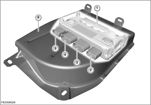
Index |
Explanation |
Index |
Explanation |
|---|---|---|---|
1 |
Control module for active steering (AL) |
2 |
Plug connection 12-pin (vehicle wiring harness) |
3 |
Plug connection 2-pin (power supply) |
4 |
Plug connection 3-pin (servomotor) |
5 |
Plug connection 12-pin (sensor and servomotor lock) |
6 |
Kick-plate housing |
Overriding gear with servomotor and servomotor lock
The overriding gear of the active steering is located on the steering gear. The overriding gear is installed in the split steering shaft. The overriding gear is a planetary gear train with 2 inputs and one output. The first input is formed by the lower steering shaft of the steering column. The second input shaft is a worm gear on the planetary transmission. The electric servomotor (actuated by the AL control module) drives the worm gear of the planetary transmission. The gear ratio from the worm to the worm gear is 20.5:1. For possible failures, the worm gear pair is designed as self-inhibiting. The worm gear pair overrides the steering angle of the direct drive-through from the steering shaft. The cumulative steering angle at the steering pinion comprises:
- Steering angle, applied at the steering wheel
- Steering angle applied by the electric servomotor
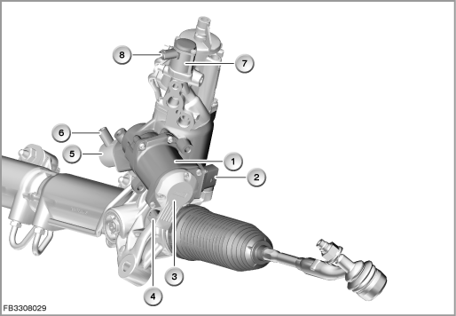
Index |
Explanation |
Index |
Explanation |
|---|---|---|---|
1 |
Active steering controller |
2 |
4-pin plug-in connection |
3 |
Motor position sensor |
4 |
3-pin plug-in connection |
5 |
Servomotor lock |
6 |
2-pin plug-in connection |
7 |
Servotronic valve (connected at the ICM control module) |
8 |
2-pin plug-in connection |
The electric servomotor on the planetary transmission with override function receives its supply from three phases (= wires) (U, V, W). In the event of a short circuit, the electric servomotor can turn a maximum of 120°. This prevents inadvertent start-up movements of the servomotor in the event of a short circuit. A temperature sensor in the control module for active steering (AL) monitors the output stage for the servomotor.
The electric servomotor lock blocks the electric servomotor:
- in the event of faults to prevent it from rotating due to external forces
- when the vehicle is at a standstill and the is engine off (not when the vehicle is at a standstill and the engine is running)
If the engine is switched off by the automatic engine start-stop function, the servomotor lock remains applied.
In the event of blocking, the servomotor lock engages in the corresponding gearing on the worm. The lock is spring-loaded, with the force of the spring countered by the power supply. Any interruption of the power supply consequently causes the lock to engage. The driver can still control the vehicle by means of the steering wheel, even if the planetary transmission with override function is locked in this way. Under these circumstances, the steering performs in much the same way as conventional steering systems. The purely mechanical transfer between the steering wheel and front wheels is always maintained.
HSR control module
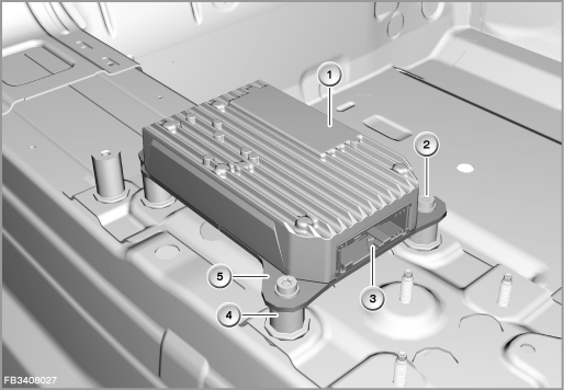
The control module for the rear axle slip angle control (HSR) is in the luggage compartment recess. The HSR control module activates the servomotor in the actuator of the rear axle slip angle control. A temperature sensor in the HSR control module monitors the output stage for the servomotor.
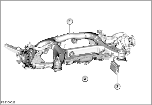
Index |
Explanation |
Index |
Explanation |
|---|---|---|---|
1 |
Rear-axle member |
2 |
Control module for rear axle slip angle control (HSR) |
3 |
Actuator for rear axle slip angle control (HSR) |
|
|
A motor position sensor and a tie rod position sensor are installed in the actuator. The signals of these sensors are evaluated by the HSR control module.
The HSR control module is connected via the control module for active steering (AL) on the FlexRay.
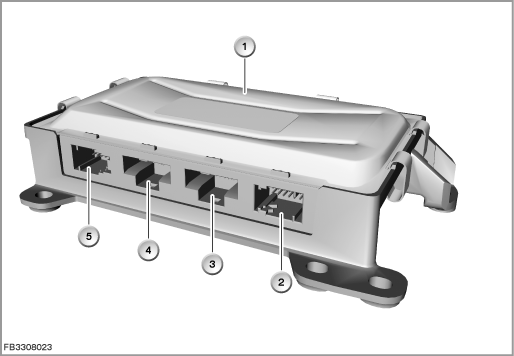
Index |
Explanation |
Index |
Explanation |
|---|---|---|---|
1 |
Control module for rear axle slip angle control (HSR) |
2 |
Plug connection 12-pin (sensors) |
3 |
Plug connection 3-pin (servomotor) |
4 |
Plug connection 2-pin (power supply) |
5 |
Plug connection 12-pin (vehicle wiring harness) |
|
|
Actuator for rear axle slip angle control
The following components are installed in the actuator:
- Servomotor
- Motor position sensor
- Tie rod position sensor
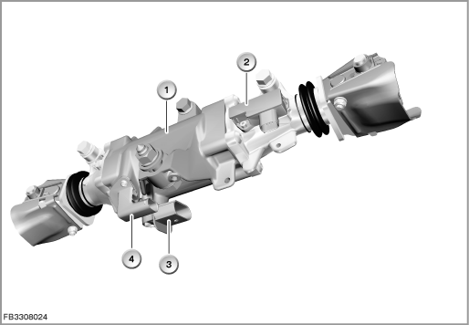
Index |
Explanation |
Index |
Explanation |
|---|---|---|---|
1 |
Actuator for rear axle slip angle control |
2 |
Plug connection for tie rod position sensor |
3 |
Plug connection for servomotor |
4 |
Plug connection for motor position sensor |
Servomotor
The electromechanical actuator consists of a servomotor that moves both tie rods via a spindle gear drive. The tie rods are connected to the track control arms. The actuator is configured for a maximum lifting movement of 8 mm, which leads to an angle of maximum 3° on the wheel. The spindle gear drive of the rear-wheel steering is designed as self-inhibiting. Following a system failure, the vehicle has the same characteristics as if designed without rear-wheel steering.
The servomotor is a brushless three-phase motor.
The servomotor on the overriding gear is supplied over 3 phases (= lines) with voltage (U, V, W).
In the event of a short circuit, the servomotor can continue rotating due to external forces (no servomotor lock present). The consequence is an inconsistent steering wheel angle of up to 45° that can be perceived by the driver!
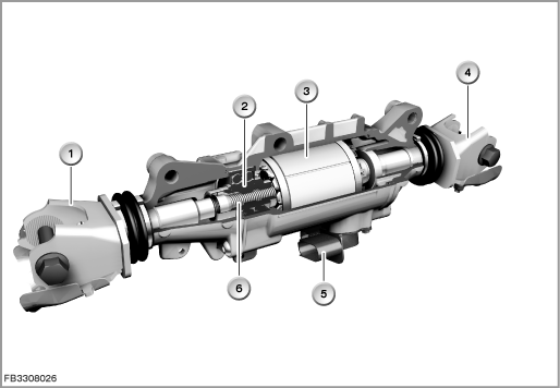
Index |
Explanation |
Index |
Explanation |
|---|---|---|---|
1 |
Tie rod joint, left |
2 |
Nuts |
3 |
Servomotor |
4 |
Tie rod joint, right |
5 |
Plug connection for servomotor |
6 |
Thread spindle |
Engine position sensor
The motor position sensor consists of a magnetoresistive element and a permanent magnet. The permanent magnet is located on the front of the rotor shaft of the servomotor. The magnetoresistive element measures the magnetic field direction horizontally and vertically. The motor-position sensor has a measuring range of 180°. The motor-position sensor supplies 2 voltage signals. A rotation through 360° is based on 2 signal periods. The two voltage signals are used to calculate the rotary position of the motor. The number of half turns is counted by the HSR control module, which stores this number in its memory when the ignition is switched off.
Tie rod position sensor
The tie rod position sensor is a non-contact position sensor (PLCD = Permanent-magnetic Linear Contactless Displacement).
The tie rod position sensor consists essentially of a special core of soft magnetic material. This core is wrapped in a coil (primary coil) along its entire length. The core has another short evaluation coil on each end. A permanent magnet approximated to the sensor leads to local magnetic saturation. This enables a position to be determined.
ICM control module
New: Sensors that used to be installed separately in the DSC sensor are now fitted in the ICM control module. The ICM control module uses these sensors to calculate variables that are important for the dynamic driving vehicle status:
- Longitudinal acceleration and vehicle inclination in longitudinal direction
- Lateral acceleration and vehicle inclination in lateral direction
- Yaw rate
The ICM control module is available as the basic variant and the High variant. The High variant differs in that it has:
- A larger microprocessor (required for calculation of the control operation of Integral Active Steering and Active Cruise Control)
- A redundant sensor system for lateral acceleration and yaw rate (safety requirement for Integral Active Steering).
Index |
Explanation |
Index |
Explanation |
|---|---|---|---|
1 |
Upper section of housing |
2 |
Mounting bolt |
3 |
Plug connection (54-pin) |
4 |
Spacer sleeve |
5 |
Lower section of housing |
|
|
The ICM control module is located on the transmission tunnel in the vicinity of the vehicle center of gravity.
System functions
The following system functions are described:
- Integral Active Steering composite system (AL with HSR)
- Distributed functions
- Servotronic
- Driving stabilization
- Snow chain detection (only BMW-approved snow chains)
Integral Active Steering composite system
The following illustration shows the composite system for the Integral Active Steering
.
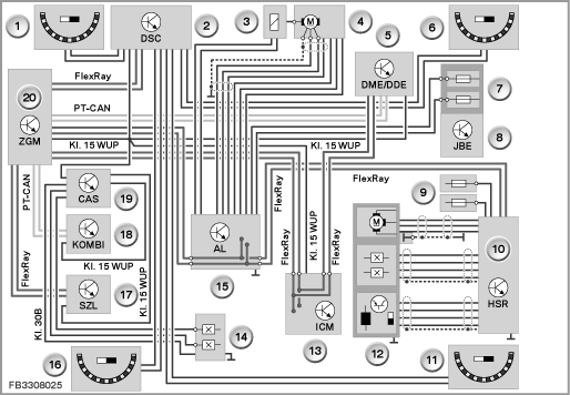
Index |
Explanation |
Index |
Explanation |
|---|---|---|---|
1 |
Wheel-speed sensor, front left |
2 |
DSC (Dynamic Stability Control) |
3 |
Servomotor lock |
4 |
Servomotor |
5 |
DME (Digital Motor Electronics) or DDE (Digital Diesel Electronics) |
6 |
Wheel-speed sensor, front right |
7 |
Front distribution box |
8 |
Junction box electronics (JBE) |
9 |
Rear distribution box |
10 |
Rear axle slip angle control (HSR) |
11 |
Wheel-speed sensor, front right |
12 |
Servomotor with motor position sensor and tie rod position sensor |
13 |
Integrated Chassis Management (ICM) |
14 |
Brake light switch |
15 |
Active Steering (AL) |
16 |
Wheel-speed sensor, rear left |
17 |
Steering Column Switch Cluster (SZL) |
18 |
Instrument cluster (KOMBI) |
19 |
Car Access System (CAS) |
20 |
Central gateway module (ZGM) |
Note! Compulsory combination of active steering and rear axle slip angle control.
The rear axle slip angle control can not be ordered as an optional equipment on its own.
Distributed functions
The Integrated Chassis Management (ICM) is the higher-level control module in which the target values of the Integral Active Steering are calculated. The ICM uses the current driving status and steering angle of the driver to calculate the target values for the variable steering-gear ratio and yaw-rate control. Once these values have been prioritized, the ICM provides resulting target values for the AL and HSR control modules. This is a specified angle that is set at the front wheels and rear wheels. Both control modules receive the target value and activate the actuator in such a way that the target value is implemented correctly. Both control modules are thus exclusively control modules for actuators.
The control modules are connected on the FlexRay. The FlexRay is routed through the AL control module to the HSR control module.
Servotronic
Both the base steering and Integral Active Steering have Servotronic. The speed-dependent steering power assistance is implemented by the Servotronic valve on the steering gear. The Servotronic valve is always controlled by the ICM control module. This means that the ICM control module also contains the logic of the Servotronic function.
The ICM control module also activates the ECO valve. This valve enables electronic adjustment of the volumetric flow of the power-steering pump.
Note! Other functional descriptions are important.
Consult the functional descriptions for the driving dynamics systems in the BMW diagnosis system.
Driving stabilization
If the vehicle tends to oversteer, for instance, when cornering, the yaw-rate control can correct the steering angle on the front wheels. This stabilizes the vehicle (with the emphasis on convenience and comfort). In this road situation, therefore, the Active Steering supports Dynamic Stability Control (DSC). DSC does not intervene unless the stabilizing effect of the steering does not suffice to counteract the tendency to yaw.
With conventional systems, the driver has to actively steer the vehicle in a straight line if the brakes are applied on a road surface with non-uniform traction levels. In such situations, the Active Steering performs this active steering intervention, so stabilizing the vehicle. Compared to pure ABS control, Active Steering with yaw moment compensation shortens the braking distance.
Snow chain detection (only BMW-approved snow chains)
It must not be possible for the customer to switch off active steering systems!
In the case of Integral Active Steering, when snow chains are mounted on the rear axle active steering intervention cannot be used on the rear wheels. When snow chains are fitted, the rear-wheel steering is disabled to ensure free wheel travel in all cases.
If snow chains are used, ”Snow chains fitted” must be set in iDrive in the settings menu. If the permitted maximum speed with snow chains of approx. 65 km/h is exceeded, the rear-wheel steering is reactivated despite the setting ”Snow chains fitted”!
Snow chain detection is computed in the HSR control module. The snow chain detection uses 2 methods.
Up to approx. 25 km/h, the signals of the height-level sensors (front left and rear left) are used. Up to 50 km/h, the signals of the wheel-speed sensors (front left and rear left) are used. The signal forms (pattern as the chain links move) are used to determine the presence of a snow chain. The individual signals are always combined by the HSR control module to form an overall criterion.
As fail-safe, the sensor signals at front right and rear right are used as back up.
Snow chain detection becomes active as follows:
- Terminal 15 ON
- Driving speed greater than approx. 4 to 6 km/h
The snow chain detection is activated but does not compute:
- Driving speed greater than approx. 65 km/h
- No snow chain detected after a certain time
There is a Check Control message for snow chain detection.
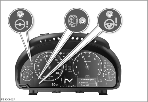
Index |
Explanation |
Index |
Explanation |
|---|---|---|---|
1 |
Fixed-position indicator lamp for active steering |
2 |
Check Control symbol for snow chain detection |
3 |
Check Control symbol for active steering |
|
|
Notes for Service department
General information
After installation of the new ICM control module, the diagnosis system must be used to commission the unit. Here, the following steps are carried out (depending on vehicle equipment):
- Calibration of the sensor system integrated in the ICM
- Calibration of the height-level sensors
- Initialization of the Integral Active Steering.
Diagnosis instructions
Note! Use the service functions.
The BMW diagnosis system provides the following service functions for the Integral Active Steering:
- Steering test
- Initialization of motor position sensor HSR
- Wheel alignment, rear axle
Path: Service functions > Chassis > Rear axle slip angle control
- Commissioning, adjustment of active steering
Path: Service functions > Chassis > Active steering
No liability can be accepted for printing or other faults. Subject to changes of a technical nature