Integrated Chassis Management
Integrated Chassis Management
There were two main objectives in the development of Integrated Chassis Management (ICM):
- To increase the performance of the individual driving dynamics systems
- To improve the interplay of the individual driving dynamics systems
In every driving situation, the most suitable actuator can now be selected and activated to influence the driving dynamics as desired. It goes without saying that simultaneous application of several actuators can also make sense.
An example of this could be brake intervention on individual wheels or an overriding steering angle provided by the Integral Active Steering.
Another task of the ICM control module is provide the dynamic driving state in the form of signals to the systems in the entire vehicle.
This is why the DSC sensor, which used to be fitted separately, has now been integrated in the ICM control module. This enables all the systems to access the same information provided by the ICM control module.
The consequence is that, especially in the case of networked systems, the causes of faults are reduced and the reliability of the systems is increased.
A particular experience for the customer is the coherent driving characteristics due the new Driving Dynamics Control. The driving dynamics switch is used to operate Driving Dynamics Control. There is a choice of 4 programs for Driving Dynamics Control:
- COMFORT
- Normal
- Sport
- SPORT+
Brief description of components
The following components are described:
- ICM control module
- Height-level sensor
- Centre console operating unit
- Servotronic valve
- ECO valve
ICM control module
New: Sensors that used to be installed separately in the DSC sensor are now fitted in the ICM control module. The ICM control module uses these sensors to calculate variables that are important for the dynamic driving vehicle status:
- Longitudinal acceleration and vehicle inclination in longitudinal direction
- Lateral acceleration and vehicle inclination in lateral direction
- Yaw rate
Initially, the sensor signals are related to the sensor housing. However, the driving dynamics systems need these variables related to the co-ordinate system of the vehicle. The ICM control module performs the necessary conversion. The correction values necessary for this are determined and stored by a calibration during commissioning of the ICM control module.
Calibration of the integrated sensors is necessary after replacement of the ICM control module. Calibration must take place while the vehicle is on a subsurface that is horizontal in longitudinal direction and lateral direction. Terminal 15 must be switched on.
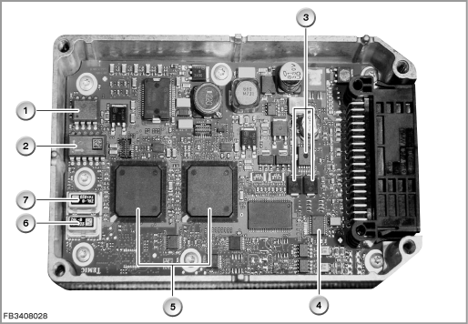
Index |
Explanation |
Index |
Explanation |
|---|---|---|---|
1 |
Redundant lateral-acceleration sensor |
2 |
Longitudinal and lateral-acceleration sensor |
3 |
Output stages for Servotronic valve and ECO valve |
4 |
Controller for FlexRay |
5 |
Microprocessors |
6 |
Yaw rate sensor |
7 |
Redundant yaw rate sensor |
|
|
The ICM control module is available as the basic variant and the High variant. The High variant differs in that it has:
- A larger microprocessor (required for calculation of the control operation of Integral Active Steering and Active Cruise Control)
- A redundant sensor system for lateral acceleration and yaw rate (safety requirement for Integral Active Steering).
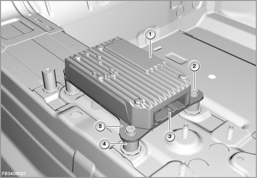
Index |
Explanation |
Index |
Explanation |
|---|---|---|---|
1 |
Upper section of housing |
2 |
Mounting bolt |
3 |
Plug connection (54-pin) |
4 |
Spacer sleeve |
5 |
Lower section of housing |
|
|
The ICM control module is located in the vicinity of the vehicle centre of gravity.
The control module is mounted on the transmission tunnel using 4 bolts and spacer sleeves made of aluminium. This mounting must connect the control module with the vehicle body without play. Otherwise, the control module housing would vibrate, which would seriously diminish the correct operation of the integrated sensor system. A second task of this mounting is to carrying off heat from the control module to the body.
Height-level sensor
Four height-level sensors (2 on the front axle, 2 on the rear axle) are connected to the ICM control module. On vehicles with electronic height control (EHC), the rear height-level sensors are 2-channel: 1 connection to the ICM control module as well as 1 connection to the EHC control module.
The height-level sensor is a non-contact sensor. The height-level sensor proportionally converts distances into an analogue voltage signal using an angle of rotation. The sensor can be rotated by 360°. The measuring range is 70° (depending on the installation location, See also 'Characteristic curve'). The signals are output as analogue electrical voltages.
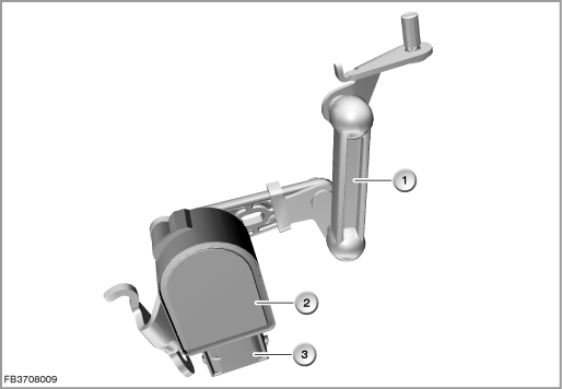
Index |
Explanation |
Index |
Explanation |
|---|---|---|---|
1 |
Coupling bar |
2 |
Height-level sensor |
3 |
6-pin plug-in connection |
|
|
Centre console operating unit
The driving dynamics switch is used to operate Driving Dynamics Control. The new Driving Dynamics Control has the following innovations: All of the drive and driving dynamics systems installed in the vehicle are activated. The central control module for this is the Integrated Chassis Management (ICM).
The driving dynamics switch and the DTC button are electrically connected to the ICM.
The following systems are influenced by Driving Dynamics Control:
- Accelerator pedal module
- Automatic transmission
- Steering
- Vertical dynamics management (VDM) via shock absorbers as well as active roll stabilization
- Dynamic Stability Control (DSC)
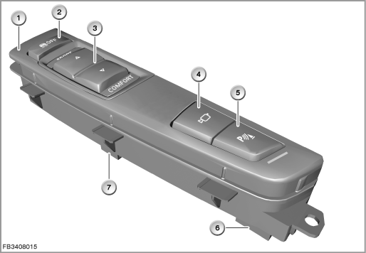
Index |
Explanation |
Index |
Explanation |
|---|---|---|---|
1 |
Centre console operating unit |
2 |
DTC button |
3 |
Driving dynamics switch |
4 |
Button for bumper camera |
5 |
PDC button with function indicator lamp as well as button for rear view camera |
6 |
4-pin plug-in connection |
7 |
6-pin plug-in connection |
8 |
|
Servotronic valve
The Servotronic controls the degree of assistance provided by the hydraulic steering as a function of the vehicle's speed. The flow of hydraulic fluid is restricted to a greater or lesser extent depending on how the Servotronic valve is actuated. Restriction of the flow depends on the current actuating the Servotronic valve.
The Servotronic valve is actuated by the ICM control module. The signals and messages required for the Servotronic are as follows:
- Road speed from the DSC control module via the bus
- Status of the engine from the DME control module
- Terminal status from the CAS control module via bus
The Servotronic valve is only activated at Terminal 15 ON and with the engine running. When the speed signal is present, the setting of the nominal current is taken from the characteristic curve.
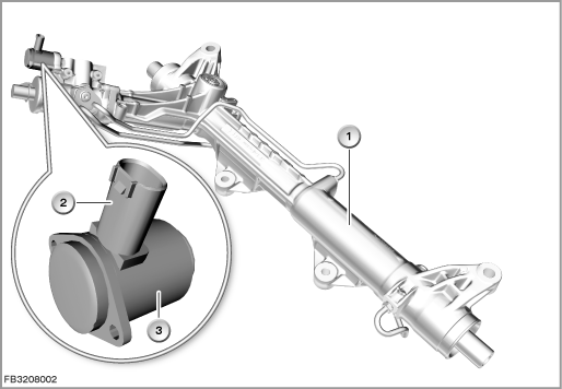
Index |
Explanation |
Index |
Explanation |
|---|---|---|---|
1 |
Rack and pinion power-steering |
2 |
2-pin plug-in connection |
3 |
Servotronic valve |
|
|
ECO valve
The power-steering pump is a vane-cell pump. The ECO valve (ECO = Electronically Controlled Orifice) is located at the power-steering pump. The ECO valve regulates the volume flow of the hydraulic fluid, thus regulating the pump's hydraulic power.
A tandem pump is installed on vehicles with Dynamic Drive. The radial pistons supply the active roll stabilization (ARS). The vane-cell pump supplies the steering.
The ECO valve in the power-steering pump regulates the volumetric flow depending on the requirement and lowers the backpressure in the hydraulic system. In this way, the ECO valve affects the power consumption of the power-steering pump. The fuel consumption and carbon dioxide emissions (CO2) for the vehicle's engine are reduced.
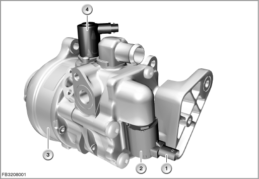
Index |
Explanation |
Index |
Explanation |
|---|---|---|---|
1 |
2-pin plug-in connection |
2 |
Servotronic valve |
3 |
Tandem pump |
4 |
Drainage coil valve |
System functions
The following system functions are described:
- The Integrated Chassis Management composite system
- Dynamic Driving Control
- Other functions
The Integrated Chassis Management composite system
The following illustration shows the composite system for Driving Dynamics Control
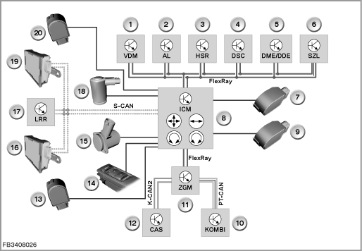
Index |
Explanation |
Index |
Explanation |
|---|---|---|---|
1 |
Vertical dynamics management (VDM) |
2 |
Active Steering (AL) |
3 |
Rear axle slip angle control (HSR) |
4 |
DSC (Dynamic Stability Control) |
5 |
Digital Motor Electronics or Digital Diesel Electronics (DME or DDE) |
6 |
Steering Column Switch Cluster (SZL) |
7 |
Height-level sensor, rear right |
8 |
Integrated Chassis Management (ICM) |
9 |
Height-level sensor, rear left |
10 |
Instrument cluster (KOMBI) |
11 |
Central gateway module (ZGM) |
12 |
Car Access System (CAS) |
13 |
Height-level sensor, front left |
14 |
Driving dynamics switch |
15 |
Servotronic valve |
16 |
Short-range sensor, left |
17 |
Long-range sensor (LLR = Long Range Radar) |
18 |
ECO valve |
19 |
Short-range sensor, right |
20 |
Height-level sensor, front right |
Dynamic Driving Control
The new Driving Dynamics Control has the following two new features:
- All of the drive and driving dynamics systems installed in the vehicle are switched at once.
- There is a choice of 4 stages. The state of the dynamic stability control is also taken into account, which means that 2 more stages are possible.
Driving Dynamics Control is operates using a new driving dynamics switch and the DTC button arranged directly in front of it. Driving Dynamics Control thus bundles the switching of many drive and driving dynamics functions. The entire vehicle behaves in exactly the way the driver expects due to the stage selected. This bundling means that the characteristics of the vehicle are considerably more distinctive and that there is less emphasis on compromises. On the other hand, a large number of individual combinations, some of which make no sense, are avoided (example: sporty steering and simultaneous comfort-oriented damping).
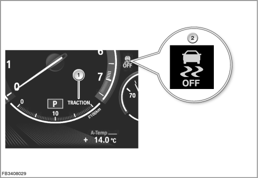
Index |
Explanation |
Index |
Explanation |
|---|---|---|---|
1 |
TRACTION message in the revolution counter |
2 |
DSC indicator lamp |
New is the display with selected DTC button. ”TRACTION” can be seen in the revolution counter of the instrument cluster. The symbol of the indicator lamp has changed as a result of legal regulations: Skidding vehicle with the labeling ”OFF”.
Other functions
Integrated Chassis Management (ICM) assumes the following functions:
- Central signal plausibility check for longitudinal and lateral acceleration, and yaw rate
- Central signal provision for driving speed, road longitudinal and lateral inclination
- Activation and control function for control modules of the active steering (AL) as well as rear axle slip angle control (HSR)
- Calculation for activation of the actuators for active steering, rear axle slip angle control and Dynamic Stability Control (DSC)
- Driver assistance function cruise control system: cruise control system with braking function as well as active cruise control with stop-and-go traffic
- Calculation for activation of the lane departure warning (TLC) as well as lane change warning (SWW)
- Central co-ordination of the display of Check Control messages for the chassis control system
- Central co-ordination of the torque request for chassis control systems
Note! Other functional descriptions are important.
For the driver assistance functions, read the corresponding functional descriptions in the BMW diagnosis system.
Notes for Service department
General information
After installation of the new ICM control module, the diagnosis system must be used to commission the unit. Here, the following steps are carried out (depending on vehicle equipment):
- Calibration of the sensor system integrated in the ICM
- Calibration of the height-level sensors
- Initialization of the Integral Active Steering.
Diagnosis instructions
Note! Use the service functions.
The BMW diagnosis system provides the following service functions for Integrated Chassis Management:
- Calibration of ICM sensor system
- Setting long-range sensor
- Setting short-range sensor
- Ride-height calibration
- Commissioning, adjustment of active steering
- Steering angle sensor calibration
- Initialization of motor position sensor HSR (= rear axle slip angle control)
- Commissioning SWW sensor system (= lane change warning)
Path: Service functions > Chassis > Integrated Chassis Management
No liability can be accepted for printing or other faults. Subject to changes of a technical nature