Single-axle self-levelling suspension
Single-axle self-levelling suspension
The ride-height control on the rear axle ensures a vehicle height and ground clearance that are independent of the load. To do so, the height of the vehicle body is raises by 2 air springs under all load conditions to a specified nominal ride-level height setting.
Brief description of components
The single-axle ride-height control comprises the following components:
EHC control module
The EHC control module (EHC = Electronic Height Control) decides whether there is a need for adjustment to compensate for changes in the load. The vehicle heights and vehicle conditions are taken into account here. The EHC control module prevents adjustments caused any other way. This makes it possible to gear the intervention to each situation as regards optimum frequency, target height, tolerance thresholds and battery load.
In addition to handling the self-levelling suspension, the EHC control module has the task of monitoring the system components and storing faults.
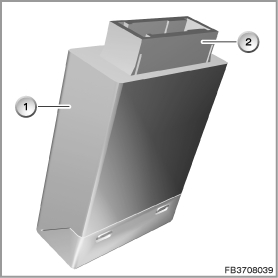
Index |
Explanation |
Index |
Explanation |
|---|---|---|---|
1 |
EHC control module |
2 |
26-pin plug-in connection |
The EHC control module recognizes the different operating conditions from the incoming signals and messages. Depending on the drive status, the EHC control module switches into the corresponding control functions.
The EHC control module processes the following signals and bus signals:
- Ride-level height of vehicle from height-level sensors located at the rear right and rear left.
- Terminal 15 ON or OFF or terminal R (bus signal with terminal status from CAS)
- Driving speed (bus signal driving dynamics from Integrated Chassis Management ICM)
- Lateral acceleration (bus signal driving dynamics from Integrated Chassis Management ICM)
- 'Engine running' signal (bus signal from DME or DDE)
- Information on the status of the doors and luggage compartment lid (bus signal with flap status from CAS, FRM, JBE)
- Kilometer reading (bus signal from the instrument cluster)
- Trailer detection (bus signal from the AHM control module)
- Status of the Tyre Pressure Monitor or Flat Tire Monitor (bus signal from the RDC control module or DSC control module).
Air supply system
The functions of the air supply unit are implemented by activation of the compressor and solenoid valves. The EHC control module controls the functions.
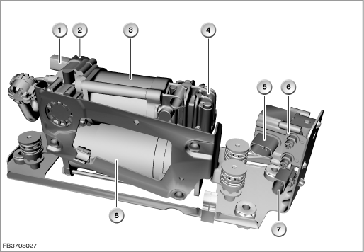
Index |
Explanation |
Index |
Explanation |
|---|---|---|---|
1 |
2-pin plug-in connection for drain valve |
2 |
Drain valve |
3 |
Air drier |
4 |
Compressor |
5 |
3-pin plug-in connection for solenoid valve block |
6 |
Solenoid valve block |
7 |
2-pin plug-in connection for electric motor |
8 |
Electric motor |
The air supply unit contains the following components:
- Electric motor for drive of the compressor
- Compressor with air drier
- Drain valve with pressure limitation function
- Solenoid valve block with 2 solenoid valves (2/2-way valves)
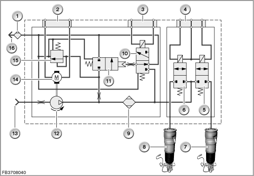
Index |
Explanation |
Index |
Explanation |
|---|---|---|---|
1 |
Air cleaner |
2 |
2-pin plug-in connection |
3 |
2-pin plug-in connection |
4 |
3-pin plug-in connection |
5 |
Solenoid valve for control of the air springs |
6 |
Solenoid valve for control of the air springs |
7 |
Air spring, rear right |
8 |
Air spring, rear left |
9 |
Air drier |
10 |
Control valve |
11 |
Drain valve with pressure limitation function |
12 |
Compressor |
13 |
Air induction |
14 |
Electric motor |
15 |
Safety valve |
16 |
Bleeding |
Compressor
The compressor is driven by an electric motor. Power is supplied to the electric motor via a relay. The relay is activated by the EHC control module until the specified nominal height is reached. The compressor temperature is monitored by a time model (stored in the EHC control module). If the maximum run time of the compressor is exceeded, other adjustments are suppressed. Once the value drops below the threshold value for switching on again, adjustments can be made again.
Air drier
The air taken in by the compressor passes over a water-absorbing filter in the air drier. This withdraws moisture from the air. As long as the air is more moist than the filter, the filter absorbs the moisture. On flowing back, the air is drier than the filter. This returns the moisture to the air and is escapes.
Solenoid valve block
The solenoid valve block contains the following valves:
- Solenoid valve for control of the rear left air spring
- Solenoid valve for control of the rear left air spring
Drain valve
The drain valve is activated by the EHC control module. The air escapes from the solenoid valve block via the drain valve through the air drier.
The pressure limitation function of the drain valve limits the pressure in the air supply unit as follows:
Maximum pressure 13.5 bar (temperature-dependent tolerance + 5 to + 6.5 bar = breakaway point if drain valve not used for longer period)
2 air springs
The air springs are integrated in the suspension struts. The air springs are surrounded by an aluminium sleeve. The air springs form the airtight and moving connection between the body and the wheel carrier. The air pressure in the air springs bears the vehicle load in each case.
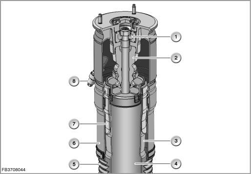
Index |
Explanation |
Index |
Explanation |
|---|---|---|---|
1 |
Shock absorber bearing |
2 |
Auxiliary spring |
3 |
Roller piston |
4 |
Controlled shock absorber |
1 |
Gaiter |
2 |
Outer guide |
3 |
Air-spring bellow |
4 |
Residual pressure retention value |
2 height-level sensors
The height sensors provide the EHC control module with information on the heights of the left and right sides of the vehicle. The level sensors relevant to EHC are fitted to the rear axle.
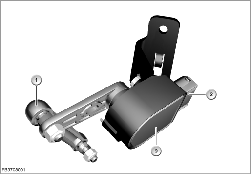
Index |
Explanation |
Index |
Explanation |
|---|---|---|---|
1 |
Coupling bar |
2 |
6-pin plug-in connection |
3 |
Height-level sensor |
|
|
The coupling bar converts the wheel lift into a rotary motion at the height-level sensor. As the spring compresses and rebounds, the output voltage for the of the height-level sensor changes linearly. On compression at the rear left, the output voltage rises. On rebound, the output voltage falls (rear right exactly vice versa, determined by the installation location).
Check Control
A fault in the single-axle self-levelling suspension is shown in the instrument cluster by means of a Check Control symbol (yellow). The text for the Check Control message can be called up in the Central Information Display (CID).
System functions
The self-levelling suspension works by feeding or extracting air into or out of the air springs.
The height sensors provide the EHC control module with information on the heights of the left and right sides of the vehicle.
If the ride heights are outside of the specified tolerance (depending on vehicle condition, e.g. engine running), the system regulates to the nominal ride-level height setting via the air supply unit.
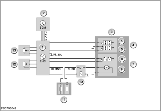
Index |
Explanation |
Index |
Explanation |
|---|---|---|---|
1 |
EHC control module |
2 |
Central gateway module (ZGM) |
3 |
Air supply system |
4 |
Solenoid valve block |
5 |
Solenoid valve for control of the rear left air spring |
6 |
Solenoid valve for control of the rear right air spring |
7 |
Compressor with attachment parts |
8 |
Drain valve |
9 |
Electric motor |
10 |
Compressor relay |
11 |
Rear distribution box |
12 |
Height-level sensor, rear left |
13 |
Height-level sensor, rear right |
|
|
Changes to the load mainly take place when the vehicle is at a standstill, before or after a journey. In order to load the vehicle, the doors or luggage compartment / rear hatch have to be opened. The system is activated when a door or the luggage compartment lid is opened. The system only switches off several minutes after the driver leaves the vehicle.
In order to distinguish load changes from other influences such as uneven roads, the signals of the height-level sensors are filtered. To ensure use in line with requirements, for each signal two filtered signals with different frequencies are calculated (low-pass filtering with fast and slow filtering).
During an adjustment, it is always the fast filtering that is used.
Slow filtering is used to monitor the control thresholds while the vehicle is being driven. This type of filtering means that vibrations produced by the road surface are filtered out.
Both sides of the vehicle are adjusted individually. This means that the target/actual comparison is also run for both sides individually. Exception: Checking the minimum height in the Pre mode and in the control function ”transposition”. With these control functions, the mean values of the left and right-hand sides of the vehicle are taken into account.
The EHC control module uses the various signals and messages to detect the various driving states. Depending on the driving states, the adapted control functions are switched accordingly.
The following control functions of the single-axle self-levelling suspension are described:
- Sleep mode
- Pre mode (temporally controlled pre-run / after-run)
- Post mode (post adjustment)
- Normal mode
- Drive mode
- Cornering
- Transposition
- Lifting platform
- Transport mode
- Production mode
Note: All of the following specified times and dimensions are examples.
The actual encoding data depends on the model series and vehicle equipment.
Sleep mode
The Sleep mode is the initial state for interventions. In the Sleep mode, no intervention takes place. Adjustments that were started in other intervention modes are cancelled when the Sleep mode takes effect.
Pre mode
In the 'Pre' mode (time-controlled pre-run or after-run), additional loads are compensated for as soon as the owner enters the vehicle and a few minutes after stopping the vehicle.
When the vehicle is locked, the after-run is shortened.
In the Pre mode, the vehicle can only be raised to its specified height if the level drops significantly below the specified height. The tolerance range for the control is approx. 60 millimetres below the average value. The tolerance range indicates when the electronics in the EHC control module make an adjustment.
This tolerance ensures that adjustments are only made in the event of large additional loads to increase ground clearance before driving away. Smaller additional loads only lead to small amounts of spring travel which are only balanced out after the engine has been started. These characteristics reduce the load on the battery.
In the Pre mode, only the average value of the two signals of the height-level sensors are analysed.
Post mode (post adjustment)
The Post mode is used to balance out any inclination before entering the Sleep mode after completion of a journey. The control function has a time limit (approx. 1 minute).
In the Post mode, adjustment is made in a defined tolerance range (± 10 millimetres).
Normal mode
The Normal mode refers to the normal operating condition of the vehicle. The Normal mode is initiated by means of the 'engine running' signal. Adjustment is made in a defined tolerance range per side (±10 millimetres, rapid filtering).
Drive mode
The Drive mode is activated in the EHC control module when a speed signal above 1 km/h is detected.
In the Drive mode, adjustment is made by means of slow filtering. In the Drive mode, e.g., different ride heights that occur as a result of the reduction in the vehicle mass due to fuel consumption are balanced out.
Cornering
The control function ”cornering” prevents adjustment when cornering is detected. The slow filtering is halted and any ongoing adjustment is cancelled.
The cornering is detected via the incoming lateral-acceleration signal (e.g. above 2 m/s2 cornering detected, below 1.4 m/s2 cornering completed). The ICM control module sends the lateral-acceleration signal via the K-CAN.
Transposition
The operating mode ”transposition” prevents balancing of any inclination when only one wheel of the vehicle drives over an obstacle. Balancing would lead to a renewed inclination of the vehicle after coming down from this obstacle and to a new adjustment.
If one wheel of a vehicle drives up onto the kerb and stops, the EHC control module changes from the Drive mode into the Normal mode. In this control function, the signals of the height-level sensors on the left and right are evaluated.
If the difference in height between the left and right side of the vehicle exceeds a certain value (e.g. 28 millimetres), a change is made to the control function ”transposition”.
In this control function, the EHC control module analyses the car height in the center of the axle.
If the vehicle is now loaded or unloaded, the value of the compression or rebound is analysed. If the value lies outside of the defined tolerance range (e.g. ± 10 millimetres), an adjustment is initiated.
The left-hand and right-hand sides of the vehicle are raised or lowered in parallel. The difference in height between the two sides remains.
When the EHC control module goes into the Drive mode, the control function ”transposition” is terminated. Any ongoing adjustment is cancelled. The control function ”transposition” is terminated when the difference in height between the left and right sides of the vehicle falls short of a specified value.
Lifting platform
In the control function ”lifting platform”, adjustments due to wheel changes or work on the lifting platform are prevented.
The following conditions trigger the ”lifting platform” control function:
- The permitted rebound path is exceeded (e.g. more than 50 millimetres, picked up by the left and/or right height-level sensor)
- The vehicle is raised slightly (rebound of e.g. less than 55 millimetres), the control operation starts and the vehicle is not lowered
The height is stored in the EHC control module.
A reset is carried out when the vehicle returns to e.g. 10 millimetres below this stored height or the Drive mode is detected.
Transport mode
In the Transport mode, the nominal height is raised (e.g. 30 mm). Increasing the ground clearance ensures safe transport of the vehicle.
Production mode
The Production mode is used for assembly on the line and prevents regulating operations.
Notes for Service department
General information
Encoding
After replacement, the EHC control module must be encoded.
Performing ride-height calibration
A ride-height calibration must be performed after the following servicing operations:
- Replacement of the control module for the single-axle self-levelling suspension (EHC control module)
- Replacement or repair of one or of both height-level sensors or their coupling bar
- Repair to the lines of the height-level sensor
For the ride-height calibration, the measured vehicle height at the rear axle (actual height on the left and right) must be entered in the BMW diagnosis system. To do so, on the BMW diagnosis system select the service function ”Ride-height calibration”.
Procedure, see repair instruction!
No liability can be accepted for printing or other faults. Subject to changes of a technical nature