Dynamic Drive
Control module for vertical dynamics management
The following functions can be added to the vertical dynamics management control module (VDM):
- vertical dynamics management
- active roll stabilization (marketing designation: Dynamic Drive)
This document describes the Dynamic Drive.
The VDM control module is activated via the terminal 15N cable by the CAS control module and is secured by a fuse (5 A). At the same time, the VDM control module is supplied with terminal 30. The VDM control module is located in the right-hand side of the vehicle interior in the footwell area of the A-pillar.
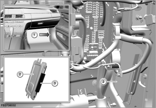
Index |
Explanation |
Index |
Explanation |
|---|---|---|---|
1 |
A-pillar trim |
2 |
Dynamic Drive control module |
3 |
Dynamic Drive connector |
|
|
Dynamic Drive prevents or reduces the vehicle's tendency to roll while cornering at high speed or during high-speed evasive manoeuvres. Vibration comfort is increased. The turn-in ability of the vehicle is optimized.
Brief description of components
The following components are described for Dynamic Drive:
- Valve block
- Hydraulic motor
- Tandem pump
- Drainage coil valve
- Oil-level switch
Valve block, Dynamic Drive
The valve block for Dynamic Drive is installed behind the front right-hand wheel arch. The valve block is electrically connected to the VDM control module. The stabilizers on the front and rear axles are split and connected in the centre to a hydraulic motor. The hydraulic motors are hydraulically activated via the valve block. This enables very rapid application of a defined torque onto the stabilizer in the desired direction.
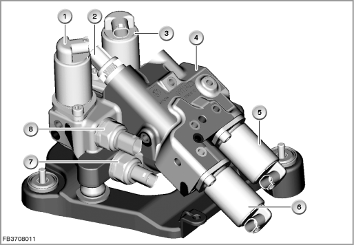
Index |
Explanation |
Index |
Explanation |
|---|---|---|---|
1 |
Pressure control valve for front axle (2-pin plug-in connection) |
2 |
Shift position sensor (3-pin plug-in connection) |
3 |
Pressure control valve for rear axle (2-pin plug-in connection) |
4 |
Valve block |
5 |
Safety valve (2-pin plug-in connection) |
6 |
Direction valve (2-pin plug-in connection) |
7 |
Pressure sensor for rear axle (3-pin plug-in connection) |
8 |
Pressure sensor for front axle 3-pin plug-in connection) |
The valve block is located in the right front wheel arch near the A pillar.
The following components of the valve block are described:
Pressure control valves on front axle and rear axle
The pressure control valves are located in the valve block. The pressure control valves are activated by the VDM control module. In the process, the hydraulic pressure (differential pressure) is set for the stabilizers (up to 180 bar). When the vehicle is being driven straight ahead, the pressure control valves are applied with preliminary current (0.35 Ampere). The oil flow flows freely to the oil reservoir. On cornering, the pressure control valves are supplied with current. The hydraulic pressure in the hydraulic motors is regulated to the target value.
Due to factors inherent in the design, the hydraulic pressure on the hydraulic motor of the front axle is greater than or equal to the hydraulic pressure on the hydraulic motor of the rear axle.
Pressure sensors on front axle and rear axle
The pressure sensors measure the hydraulic pressure to the stabilizers on the front and rear axles. The sensor signals (voltage) are sent to the VDM control module.
The pressure in the return line to the oil reservoir is not monitored (circulating flow of approx. 2 bar).
Note! Use the service function.
The BMW diagnosis system has a service function to learn the deviation of the pressure sensors from the zero point (approx. 0.7 Volts): Chassis > Dynamic Drive > Learn sensor system.
Condition: Engine off.
Direction valve
The direction valve is activated by the VDM control module. The direction valve sets the direction of the hydraulic fluid for right-hand and left-hand bends as well as of the return flow of oil. The 4-2 directional control valve ”swaps” the delivery end towards the stabilizer. The direction valve is the component of the active roll stabilization where safety is most critical. This is why the direction valve is monitored by a separate sensor.
Shift position sensor
The shift position sensor monitors the position of the direction valve. The shift position sensor works according to the Hall effect. There is a magnetic hollow cylinder on the direction valve. The shift position sensor protrudes into this cylinder.
This enables the shift position sensor to detect the following 2 positions:
No activation, activation curve (0.7 Volts, intermediate range 3.0 Volts, 4.2 Volts).
The sensor signals are sent to the VDM control module.
Safety valve
The safety valve is activated by the VDM control module. Without current, it blocks off the hydraulic motor on the front axle (hydraulically blocked).
Under the following conditions, the safety valve is without current:
Interruption of the power supply or a system fault.
The hydraulic motor on the rear axle is also hydraulically connected to the return line to the oil reservoir. This limits the system pressure and creates a circulating flow.
Structure and inner circuit
The shift position sensor as well as the two pressure sensors are supplied with current by the VDM control module (preliminary application of current 0.35 Ampere, maximum 2.5 Ampere).
The pressure control valves are activated by the VDM control module (pulse-width modulated, 5 to 95%).
The direction valve and the safety valve is either supplied with current or not (activated or not activated).
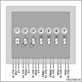
Index |
Explanation |
Index |
Explanation |
|---|---|---|---|
1 |
Pressure sensor, front axle |
2 |
Pressure sensor, rear axle |
3 |
Shift position sensor |
4 |
Front axle pressure control valve |
5 |
Rear axle pressure control valve |
6 |
Directional control valve |
7 |
Safety valve |
|
|
Pin assignments
Pin |
Explanation |
|---|---|
Terminal 31E |
Terminal 31, electronics ground |
SIG1 |
Shift position sensor signal |
5 V |
Power supply for pressure sensor, front axle |
Terminal 31E |
Terminal 31, electronics ground |
SIG2 |
Pressure sensor signal, front axle |
5 V |
Power supply for pressure sensor, rear axle |
Terminal 31E |
Terminal 31, electronics ground |
SIG3 |
Pressure sensor signal, rear axle |
5 V |
Power supply for shift position sensor |
PWM1 |
Activation of pressure control valve for front axle (pulse-width modulated) |
Terminal 31E |
Terminal 31, electronics ground |
PWM2 |
Activation of pressure control valve for rear axle (pulse-width modulated) |
Terminal 31E |
Terminal 31, electronics ground |
SIG2 |
Activation signal for direction valve |
Terminal 31E |
Terminal 31, electronics ground |
SIG3 |
Activation signal for safety valve |
Terminal 31E |
Terminal 31, electronics ground |
Target values and signal path of pressure sensors
The signal for evaluation of hydraulic pressure depends on the pressure. The measuring range of approx. 0.5 - 4.5 Volts corresponds to a hydraulic pressure of 0 bar to 200 bar.
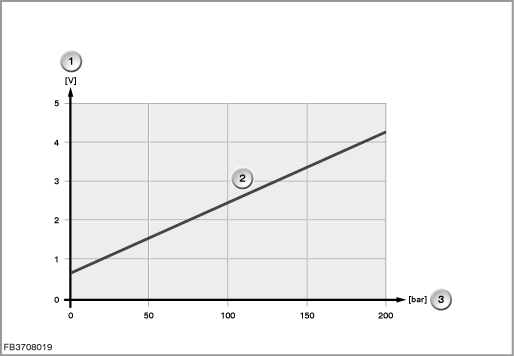
Index |
Explanation |
Index |
Explanation |
|---|---|---|---|
1 |
Signal voltage |
2 |
Characteristic curve for pressure sensors on front axle and rear axle |
3 |
Hydraulic pressure |
|
|
Observe the following target values for the components on the valve block:
Variable |
Value |
|---|---|
Power supply for pressure sensors and shift position sensor |
5 V |
Pressure control valves, preliminary current applied |
0.35 A |
Response time of direction valve |
approx. 30 ms |
Maximum stabilization torque at the hydraulic motor (rear axle) |
approx. 800 Nm |
Supply rate of tandem pump |
5.2 to 9 l/min |
Temperature range |
-40 to 140 °C |
Failure of the component
If one of the components on the valve block fails, the following behaviour is to be expected:
- Fault memory entry in the control module for vertical dynamics management (VDM)
- Check Control message in the instrument cluster
Active anti-roll bars
The active anti-roll bars are vertically split in the middle. The active anti-roll bar consists of a hydraulic motor and, attached to it, the two halves of the anti-roll bar with press-fitted roller-bearing mountings. The hydraulic motor shaft and housing are each attached to one half of the anti-roll bar. In the hydraulic motor, the opposing chambers are linked. This means the chambers each have the same pressure. Two chambers are supplied with high pressure via one connection. The two other chambers are connected to the return line to the expansion tank. Variation of the pressure varies the force generated by the motor. That force produces torque which rotates the shaft relative to the housing. As one half of the anti-roll bar is attached to the shaft and the other to the housing, the two halves of the anti-roll bar then twist in opposite directions to one another. The momentum that this creates counteracts / stabilizes the rolling motion. The maximum system pressure is 180 bar.
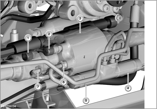
Index |
Explanation |
Index |
Explanation |
|---|---|---|---|
1 |
Pressure relief valve with air filter flap |
2 |
Pressure relief valve with air filter flap |
3 |
Front hydraulic motor |
4 |
Pulsation damper |
5 |
Pulsation damper |
6 |
Hydraulic connection |
7 |
Hydraulic connection |
|
|
Tandem pump
Depending on the engine version and equipment fitted, the fitted tandem pumps are flanged onto the engine. The tandem pump supplies the oil circuit of the Dynamic Drive as well as the power steering. The pump consists of a radial piston for the Dynamic Drive system and a vane pump for the power steering. Dynamic Drive and the power steering share a common oil cooler and oil reservoir.
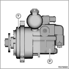
Index |
Explanation |
Index |
Explanation |
|---|---|---|---|
1 |
Radial piston section of the tandem pump |
2 |
Vane cell section of the tandem pump |
Drainage coil valve
The drainage coil valve is attached to the tandem pump.
When the vehicle is being driven straight ahead, the volumetric flow of the tandem pump is throttled on the intake side by the application of current. This lowers the pressure of the circulating flow. The tandem pump consumes less power. This lowers CO2 emissions.
Function of drainage coil valve
The oil flow flows before the tandem pump through the drainage coil valve. The control module for vertical dynamics management activates the drainage coil valve when the vehicle is being driven straight ahead. Activation is carried out when the vehicle is being driven straight ahead as well as when the vehicle is stationary (engine running). This lowers the loss due to unnecessary pump output.
The delivery volume of the tandem pump is proportional to the speed provided the speed lies below the breakaway speed of the tandem pump
(engine speed approx. 1000 rpm).
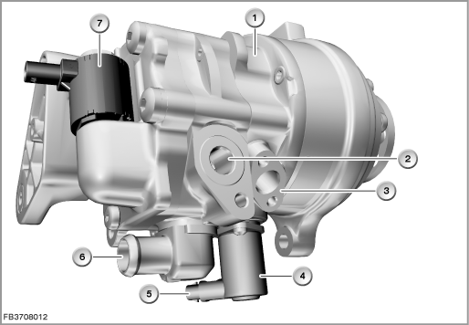
Index |
Explanation |
Index |
Explanation |
|---|---|---|---|
1 |
Tandem pump (power-steering pump and active roll stabilization) |
2 |
Connection for radial piston pump |
3 |
Connection for vane-type pump |
4 |
Drainage coil valve |
5 |
2-pin plug-in connection |
6 |
Supply to tandem pump |
7 |
ECO valve (power-steering pump) |
|
|
Structure and inner circuit
The drainage coil valve is connected by means of a 2-pin plug-in connection.
The drainage coil valve is a solenoid valve. The VDM control module supplies the drainage coil valve with current (approx. 0.85 Ampere).
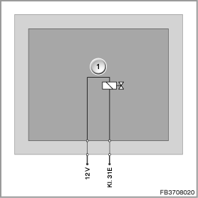
Index |
Explanation |
Index |
Explanation |
|---|---|---|---|
1 |
Drainage coil valve |
|
|
Pin assignments
Pin |
Explanation |
|---|---|
12 V |
Power supply drainage coil valve |
Terminal 31E |
Terminal 31, electronics earth for drainage coil valve |
Characteristic curve and target values for tandem pump
During idling, the pump speed is approx. 750 rpm. At this idle speed, the tandem pump delivers a volumetric flow of approx. 5 l/min at approximately 3 bar. This ensures adequate system dynamics even at idle speed. At a pump speed of 1250 rpm, the maximum volumetric flow is limited to 9 l/min.
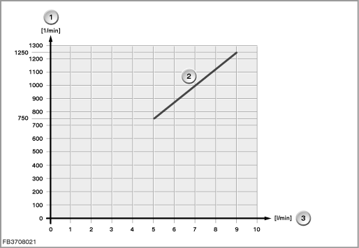
Index |
Explanation |
Index |
Explanation |
|---|---|---|---|
1 |
Pump speed |
2 |
Characteristic curve for tandem pump |
3 |
Volumetric flow |
|
|
Observe the following target values for the drainage coil valve:
Variable |
Value |
|---|---|
Voltage range |
8 to 16 V |
Response time at 20 °C and 13 V |
≤ 40 ms |
Current consumption at 25 °C and 13 V |
approx. 1 A |
Temperature range |
-40 °C to 140 °C |
Oil reservoir and oil-level switch
The oil reservoir contains an oil filter and an oil-level switch with float. In contrast to the oil-level switch, the oil filter cannot be replaced separately. A dipstick that enables a check of the oil level is attached to the screw cap.
The oil-level switch detects whether the required oil level in the oil reservoir is exceeded or undershot. The VDM control module sends the signal on the bus system to the instrument cluster. The instrument cluster issues a Check Control message. Normal motion of the oil in the oil reservoir does not lead to a Check Control message.
There is a permanent magnet in the moving float; this triggers the reed contact in the oil-level switch firmly fitted in the reservoir. Here, the reed contact converts the float movement into an electrical signal. If the oil level is above the minimum level, the reed contact is closed (approx. 10 mm below the MIN mark).
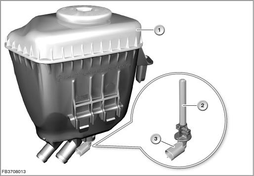
Index |
Explanation |
Index |
Explanation |
|---|---|---|---|
1 |
Oil tank |
2 |
Oil-level switch |
3 |
2-pin plug-in connection |
|
|
On the oil-level switch, short circuit or break in wiring cannot be detected. A break in wiring is interpreted as oil loss. A short circuit is not detected.
Structure and inner circuit
The reed contact has the effect of a switch. If the reed contact is activated, ground is switched through to the VDM control module.
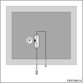
Index |
Explanation |
Index |
Explanation |
|---|---|---|---|
1 |
Reed contact in the oil-level switch |
|
|
Pin assignments
Pin |
Explanation |
|---|---|
SIG |
Reed contact signal |
Characteristic curve for filter element as well as bypass valve and target values
The oil reservoir contains a mechanical bypass valve that opens if the filter element is soiled. The bypass valve opens at approx. 3 bar overpressure.
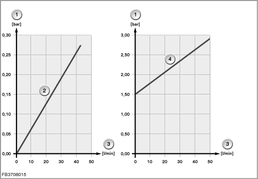
Index |
Explanation |
Index |
Explanation |
|---|---|---|---|
1 |
Differential pressure |
2 |
Characteristic curve for flow through filter element |
3 |
Volumetric flow |
4 |
Characteristic curve for flow through bypass valve |
Observe the following target values for the oil-level switch:
Variable |
Value |
|---|---|
Maximum current consumption |
15 mA |
Maximum contact resistance |
500 m |
Temperature range |
-40 °C to 120 °C |
Failure of the component
If the oil-level switch fails, the following behaviour is to be expected:
- Fault memory entry in the VDM
- Output of a Check Control message in the instrument cluster
- Fail-safe, steering power assistance also affected
General information
On checking the oil level, the influence of the oil temperature must be taken into account (volume expansion). There is a ”MAX” mark on the oil dipstick. The mark indicates the maximum permitted oil level measured at room temperature (20 °C). Due to heat expansion, at oil temperatures of 50 to 70 °C the oil level is approx. 15 mm above the mark. With regard to the oil level, follow the repair instructions.
Vehicles without active roll stabilization can be recognized by the lack of oil-level switch.
Oil cooler
The oil cooler keeps the oil temperature below 120 °C. The oil temperature is allowed to rise to a maximum of 135 °C for short periods.
Notes for Service department
Warning! Rolling motion on commissioning
During commissioning, the vehicle performs very strong and rapid rolling motions. For this reason, no persons may be located directly at the vehicle, particularly in the proximity of moving vehicle components. There must be no objects underneath the vehicle or in the wheel arches! The commissioning procedure may only be carried out with the vehicle standing of a firm, flat surface with all four wheels on the ground. Under no circumstances may the commissioning be carried out when the vehicle is on the following surfaces:
- Lifting platforms
- Wheel alignment units
- Shock absorber test units
- Brake test units
- Power output test units
Disregarding these instructions could put lives at risk!
General information
After opening the system hydraulics (valve block, hydraulic motors, lines), run commissioning.
After encoding or programming the Dynamic Drive control module, commissioning is also required.
Diagnosis instructions
Commissioning
The purpose of commissioning is to learn the parameters and zero point of all sensors. Commissioning is divided into 5 phases and it takes around 25 seconds.
- Check of direction valve
- Low pressure test
- Front axle high pressure test
- Rear axle high pressure test
- Pressure control valve test
Note! Temperature on commissioning
The oil temperature is an important parameter for the commissioning. The commissioning procedure (by means of diagnosis command) must not be carried out at extreme temperatures (ambient and system temperatures).
Notes on encoding / programming
After encoding or programming the control module, commissioning is to be run.
Information on Check Control messages
The following warnings and their causes can appear as Check Control messages in the CID:
Message: Driving comfort restricted!
With the warnings:
- Driving comfort restricted!
the Dynamic Drive system has been switched off.
NB: the vehicle tilts more strongly in bends than a vehicle without the Dynamic Drive System. Precondition for continued driving to the next workshop:
- Lower cornering speed
- No significant oil loss.
Possible causes of the warning message:
- Defect on the front axle pressure sensor
- Defect in the pressure build-up (pump)
- Defect in at least one active stabilizer bar
- Fault in the Dynamic Drive
In order to be able to pinpoint the cause more exactly, read the fault memory and run through the displayed test plan. When the fault has been remedied, clear the fault memory.
Message: Steering fault! Stop the vehicle carefully
With the warning:
- Steering fault! Stop the vehicle carefully
the driver is informed that the vehicle has suffered oil loss in the chassis and steering system.
In this case, it is not possible to continue driving to the next workshop.
Possible causes of the warning message:
In order to be able to pinpoint the cause more exactly, read the fault memory and run through the displayed test plan. When the fault has been remedied, clear the fault memory.
Message: Restricted cornering characteristics!
With the warning:
- Restricted cornering characteristics!
the driver is notified that the chassis stabilization from Dynamic Drive is restricted, but it is possible to continue driving.
A workshop should be contacted at the next opportunity.
Possible causes of the warning message:
- Defective CAN message (driving speed)
- Defective lateral-acceleration sensor
- Fault in the rear-axle circuit
- Fault during the Predrive Check
In order to be able to pinpoint the cause more exactly, read the fault memory and run through the displayed test plan. When the fault has been remedied, clear the fault memory.
No liability can be accepted for printing or other faults. Subject to changes of a technical nature