Steering column switch cluster
Steering Column Switch Cluster (SZL)
The steering column switch cluster (SZL) is a mechanical and electrical interface from the steering wheel to the vehicle. The SZL has a fixed mechanical connection to the steering column. Over and above this purely mechanical connection, the steering column switch cluster is electrically connected via bus systems or directly to components.
The version of the steering column switch cluster (SZL) depends on the options fitted.
The following optional extras expand the version involved:
- Cruise control with brake function or active cruise control
- Vibration actuator for lane departure warning or lane change warning
- Steering wheel heater
Interfaces to steering column switch cluster
The steering column switch cluster has steering column stalks on the right and left. The right-hand steering column stalk is for operation of the functions of the wipe-wash system. The left-hand steering column stalk is for operation of the high beam or turn signal lamps as well as the functions of the onboard computer.
An optical steering-angle sensor is installed in the steering column switch cluster. The steering-angle sensor uses a non-contact optical measuring system for steering-angle detection. The steering column switch cluster receives the button signals of the steering wheel directly or via the LIN bus. These signals are forwarded by the steering column switch cluster to each control modules.
The signals (e.g. of the buttons for volume adjustment of the radio) are sent by the steering column switch cluster across the FlexRay. The steering column switch cluster receives the signal to activate the vibration actuator, for example, across the FlexRay.
The steering column switch cluster forwards the trigger signal of the driver's airbag directly to the priming caps of the airbag.
The SZL evaluates the button for the electrical steering column adjustment. The requests are output across the FlexRay. The steering column switch cluster also evaluates the button for the steering wheel heating. The steering column switch cluster sends this signal across the LIN bus to the steering wheel electronics.
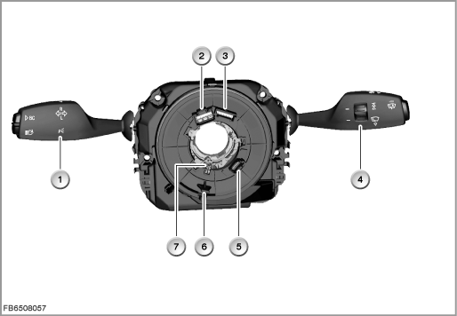
Index |
Explanation |
Index |
Explanation |
|---|---|---|---|
1 |
Steering column stalk, turn signal/high beam lever |
2 |
Plug connection to the priming caps of the airbag |
3 |
Plug connection for horn switch, multifunction buttons and steering wheel electronics |
4 |
Steering column stalk, wiper switch |
5 |
Plug connection, vibration actuator, power supply |
6 |
Steering wheel driver |
7 |
Stop bolt, steering column switch cluster |
|
|
Brief description of components
The following components are described for the steering column switch cluster (SZL):
Steering column stalk, turn signal/high beam lever
The steering-column lever on the left of the steering column has the following functions:
- High-beam assistant button
- Onboard computer button
- Direction indicator lights
- Headlight flasher
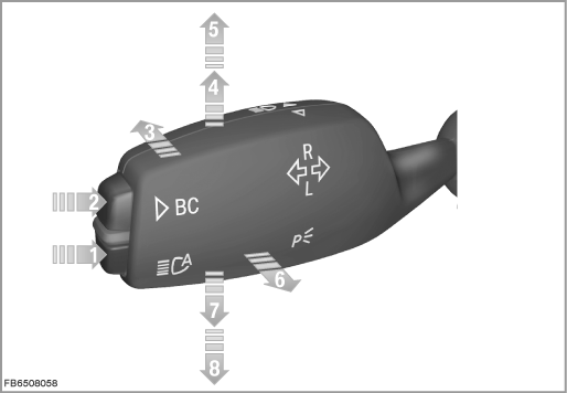
Index |
Explanation |
Index |
Explanation |
|---|---|---|---|
1 |
High-beam assistant button |
2 |
Onboard computer button |
3 |
High beam |
4 |
Triple turn signal for turn signal lamps, passenger's side |
5 |
Continuous flashing for turn signal lamps, passenger's side |
6 |
Headlamp flasher |
7 |
Triple turn signal for turn signal lamps, driver's side |
8 |
Continuous flashing for turn signal lamps, driver's side |
Depending on the position of the steering column stalk, the steering column switch cluster generates the switch signals. The switch signals are made available by the steering column switch cluster across the FlexRay.
The footwell module receives the requests of the turn signal/high beam lever as well as the button for the high-beam assistant.
Pressing the onboard computer button in an axial direction triggers the requests for the onboard computer. The SZL sends the requests to display the onboard computer functions across the FlexRay.
In the case of vehicle equipment without the high-beam assistant, the button on the steering column stalk turn signal/high beam lever is not required. A large button is used instead.
Steering column stalk, wiper switch
The steering-column lever on the right of the steering column has the following functions:
- Windscreen washer system, windscreen
- Windscreen wiper
- Rain-light-solar-condensation sensor button
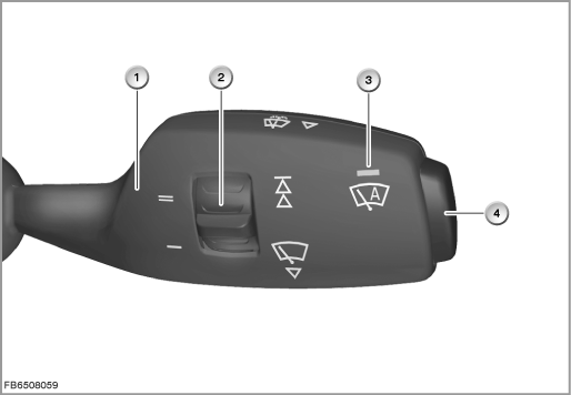
Index |
Explanation |
Index |
Explanation |
|---|---|---|---|
1 |
Steering column stalk, wiper switch |
2 |
Intensity of rain-light-solar-condensation sensor |
3 |
Function indicator, automatic wiping activated |
4 |
Rain-light-solar-condensation sensor button |
The steering column stalk is exclusively for the wipe-wash system. All requests for the wipe-wash system are picked up in the steering column switch cluster. The SZL sends the requests across the FlexRay to the junction box electronics (JBE). The junction box electronics execute the requests.
Redundant signal
The signals from the steering column stalk turn signal/high beam lever for turn signal lamps as well as headlight flasher are transferred across the FlexRay. To increase the availability, the SZL is directly connected by a cable to the footwell module (FRM). The signals - e.g. for the headlight flasher or turn signal lamps - are transferred redundantly across this cable.
Steering angle sensor
The steering angle as well as the steering-angle speed are picked up by a non-contact optical measuring system, the optical steering-angle sensor.
The data of the optical steering-angle sensor are processed by the electronics in the steering column switch cluster. These data are sent across the FlexRay to the Integrated Chassis Management (ICM).
The steering-angle sensor picks up the following variables:
- Steering angle
- Steering-angle speed (calculated in the SZL)
- Steering-wheel turns
Multifunction steering wheel
The left-hand button pad in the multifunction steering wheel has the following functions:
- Setting the desired driving speed
- Cruise control with brake function or active cruise control
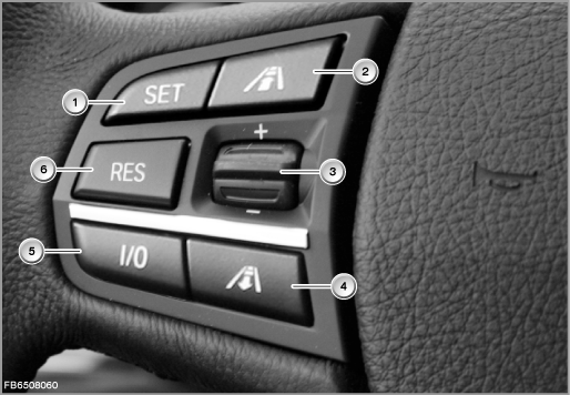
Index |
Explanation |
Index |
Explanation |
|---|---|---|---|
1 |
Set button |
2 |
Button 'Reduce distance', active cruise control (ACC) |
3 |
Rocker switch |
4 |
Button 'Increase distance', active cruise control (ACC) |
5 |
Switch cruise control to stand-by or switch off |
6 |
'Resume' button or calling up the stored speed |
The right-hand button pad in the multifunction steering wheel has the following functions:
- Scan audio functions
- Telephone
- Voice input
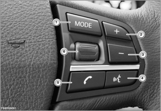
Index |
Explanation |
Index |
Explanation |
|---|---|---|---|
1 |
MODE button |
2 |
Toggle switch + |
3 |
Toggle switch - |
4 |
Hands-free mode button |
5 |
Telephone button |
6 |
Knurled wheel for selection list (e.g. in the instrument cluster) |
Vibration actuator (optional extra)
The control module for camera-based driver assistance systems (KAFAS) requests activation of the vibration actuator via the PT-CAN. The central gateway module (ZGM) implements the signal on the FlexRay. In this way, the Integrated Chassis Management (ICM) receives the request for activation. The ICM coordinates activation of the vibration actuator.
The steering wheel electronics evaluate the request. The steering wheel electronics activate the vibration actuator and monitor its function. The steering column switch cluster provides notification of a defect in the vibration actuator or steering wheel electronics across the FlexRay.
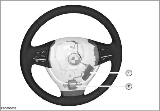
Index |
Explanation |
Index |
Explanation |
|---|---|---|---|
1 |
Steering wheel module |
2 |
Vibration actuator |
Steering column adjustment and steering wheel heating
The button for the steering column adjustment can be moved in four directions. It can be used to raise or lower the steering column or to set the distance to the driver.
The steering column switch cluster evaluates the status of the button. The SZL forwards this status to the footwell module. The signal is sent across the FlexRay to the central gateway module (ZGM). The ZGM sends the signal on the K-CAN2 to the footwell module (FRM). The footwell module activates the drive of the steering column adjustment accordingly. The activation and function are monitored by the footwell module.
The button for steering wheel heating is evaluated by the electronics of the steering column switch cluster. The electronics in the SZL send a request across the LIN bus to the steering wheel electronics to switch the steering wheel heating on or off. The steering wheel electronics switch the steering wheel heating on and monitor its function. The steering wheel heating has an NTC resistor. The purpose of this resistor is to control the temperature of the steering wheel heating.
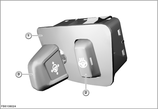
Index |
Explanation |
Index |
Explanation |
|---|---|---|---|
1 |
Switch block |
2 |
Steering wheel heating button |
3 |
Steering column calibration |
4 |
|
Functional networking
The recorded and calculated data of the steering column switch cluster are forwarded across the FlexRay to the corresponding control modules. The steering column switch cluster can be diagnosed via the central gateway module with the BMW diagnosis system. Information on the diagnosis can be called up via the FlexRay.
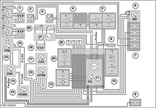
Index |
Explanation |
Index |
Explanation |
|---|---|---|---|
1 |
Drive for steering column adjustment, horizontal |
2 |
Rocker switch on the left |
3 |
Rocker switch on the right |
4 |
Multifunction steering wheel switch block, left |
5 |
Multifunction steering wheel switch block, right |
6 |
Junction box electronics (JBE) |
7 |
Front distribution box |
8 |
Fanfare horn button |
9 |
Rear distribution box |
10 |
Wiper switch |
11 |
Steering Column Switch Cluster (SZL) |
12 |
Switch for steering column adjustment and steering wheel heating |
13 |
Instrument cluster (KOMBI) |
14 |
Central gateway module (ZGM) |
15 |
Crash safety module (ACSM) |
16 |
Footwell module (FRM) |
17 |
Car Access System (CAS) |
18 |
Vibration actuator |
19 |
Drive for steering column adjustment, vertical |
20 |
Steering wheel heating with temperature sensor |
21 |
Steering wheel module |
|
|
Notes for Service department
General information
The steering-angle sensor is fixed in the SZL due to its design.
Care should be taken when replacing the steering column switch cluster or working on the steering column and the repair instructions should be followed.
Diagnosis instructions
A service function is available in the BMW diagnosis system for the steering-angle sensor adjustment.
The steering column switch cluster (SZL) can only be ordered as a complete new component. After replacement, the steering-angle sensor must be calibrated.
Use the following path: Service functions -> Chassis -> Steering-angle sensor
Place the steering wheel straight ahead from a visual point of view. The front wheels must be in the straight-ahead position.
No liability can be accepted for printing or other faults. Subject to changes of a technical nature