Instrument cluster
New technology is used for the instrument cluster:
Black Panel.
This is a panel coated on the back with black foil. The Black Panel covers the entire area of the instrument cluster (High variant). The remaining area is designed in such a way that the symbols of the indicator lamps are not visible when switched off. (Basic version)
The two large accentuation rings for the speedometer and revolution counter are galvanized. The two small dial areas for the fuel gauge and engine oil temperature are also galvanized. When switched off, the active areas of the displays are not visible.
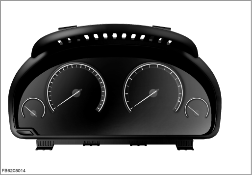
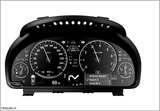
Brief description of components
The following components are described for the instrument cluster:
TFT display
A horizontal TFT display with the resolution 960 x 160 pixels is integrated in the instrument cluster below the dials. The large analogue dials are open in a downward direction. These dials are closed by graphics of the display.
Outside temperature sensor
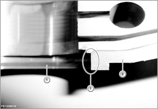
The outside temperature sensor supplies the value for the temperature outside the car to the instrument cluster. The outside temperature is shown on the liquid-crystal display. Instrument resolution is 0.5 °C (1 °F). The value for outside temperature is also made available to other control modules via the K-CAN. The signal from the outside temperature sensor is digitized in the instrument cluster. A calculation model dampens the effect of the waste heat from the engine compartment on the signal. At higher driving speed or lower engine temperature, lower damping is set. The real outside temperature value can only be expected to be reliable as of a driving speed of approx. 80 km/h.
JBE: junction box electronics
The distribution box on the Junction Box electronics supplies the instrument cluster with terminal 30F as well as terminal 30B.
The Junction Box electronics (JBE) also delivers various required signals on the bus system (K-CAN2 -> central gateway module ZGM -> PT-CAN) to the instrument cluster.
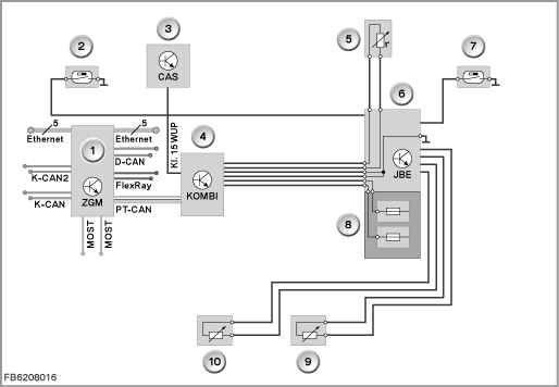
Index |
Explanation |
Index |
Explanation |
|---|---|---|---|
1 |
Central gateway module (ZGM) |
2 |
Coolant level switch |
3 |
Car Access System (CAS) |
4 |
Instrument cluster (KOMBI) |
5 |
Outside temperature sensor |
6 |
Junction box electronics (JBE) |
7 |
Washer fluid level switch |
8 |
Front distribution box |
9 |
Fuel gauge sensor, right |
10 |
Fuel gauge sensor, left |
Tank fill level sensor
The fuel tank contains two fuel-level sensors. Each fuel-level sensor sends a signal indicating the amount of fuel in the tank. A value is obtained by adding the two signals. The fuel-level sensors are connected to the Junction Box electronics (JBE). The signal is transmitted to the instrument cluster on the K-CAN2.
Note! Comply with repair instructions.
The left-hand fuel-level sensor cannot be replaced separately.
Coolant level switch
The coolant-level switch sends a signal if the coolant level is too low (Reed contact). The information is output on the TFT display in the form of a Check-Control message. The coolant level sensor is connected to the junction box electronics (JBE). The signal is transmitted to the instrument cluster on the K-CAN.
Washer fluid level switch
The washer fluid level switch sends a signal when the washer fluid level is too low. The information is output on the TFT display in the form of a Check-Control message. The washer fluid level switch is connected to the junction box electronics (JBE). The signal is transmitted to the instrument cluster on the K-CAN2.
Acoustic transmitter
The acoustic generator in the instrument cluster (KOMBI) issues acoustic signals for the following functions:
- Flashing
- Hazard warning lights
The volume is speed-dependent.
Onboard computer button
The onboard computer button is electrically connected to the steering column switch cluster (SZL). The signal is forwarded on the FlexRay to the central gateway module (ZGM). The instrument cluster receives the signal on the PT-CAN from the central gateway module.
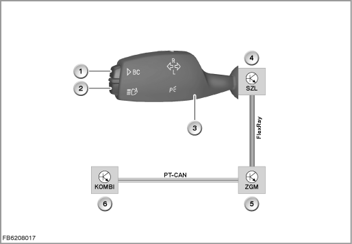
Index |
Explanation |
Index |
Explanation |
|---|---|---|---|
1 |
Onboard computer button |
2 |
High-beam assistant button |
3 |
Turn indicator / main-beam switch |
4 |
Steering Column Switch Cluster (SZL) |
3 |
Central gateway module (ZGM) |
6 |
Instrument cluster (KOMBI) |
The onboard computer functions can be called up by briefly pressing the onboard computer button on the steering column stalk. Pressing the onboard computer button again displays the information in the following order:
- Range
- Average fuel consumption
- Average speed
- Distance (with route guidance activated)
- Estimated time of arrival (with route guidance activated)
- Date
- Road sign detection
System functions
The following system functions are described for the instrument cluster:
- Standby
- Operating voltage range
- Damping the outside temperature value
- Brightness control
- Set speed for cruise control
- Redundant data storage
Standby
Operational status (standby) depends on the terminal.
- Terminal 30B (base operation) and terminal 30F (failure)
The instrument cluster is connected via the junction box at terminal 30B and 30F. The terminal status (terminal R or terminal 15) is made available to the instrument cluster via the bus system. With terminal 30 (terminal R Off), the instrument cluster is in the standby mode. Pressing the reset button wakens the instrument cluster to display the following: distance recorder, clock, outside temperature, fuel level (can be encoded). The display goes out after 25 seconds. - Terminal R
With terminal R On, the following are evaluated: turn indicator / high-beam switch and fuel-level sensor. The time and outside temperature appear in the TFT display. The on-board computer functions can be started using the onboard computer button (display unlimited in time). - Terminal 15
When terminal 15 is switched ON, a pre-drive-check is executed on the permanent indicator and warning lights. - Terminal 50 (starter motor)
During the engine start, the on-board supply voltage can fall to such a degree that the internal power supply (6 Volts) can no longer be maintained. In this case, no analog signals are evaluated. No memory operations are executed (in the EEPROM), either.
Operating voltage range
The operating voltage range is from 9 to 16 Volts. At a voltage below 7.5 Volts, undervoltage is detected. At a voltage above 16 Volts, no analog inputs are evaluated.
Damping the outside temperature value
The computation model in the instrument cluster compensates for effect that the residual heat from the engine compartment has on the outside temperature signal. This means the increase in temperature is delayed.
The input variable for the calculation model are:
- Road speed
- Coolant temperature
- Status engine on/off
- Outside temperature
A drop in the outside temperature is adopted and not damped. The engine and the body cannot be colder than the ambient temperature.
Note! Under certain circumstances, an incorrect display of the outside temperature is physically unavoidable.
With certain driving profiles, the display deviates from the real value due to damping. In the event of a customer complaint, this behaviour must be explained as the state of the art.
Example of damping the outside temperature:
Motorway driving, subsequent city traffic, the traffic jam
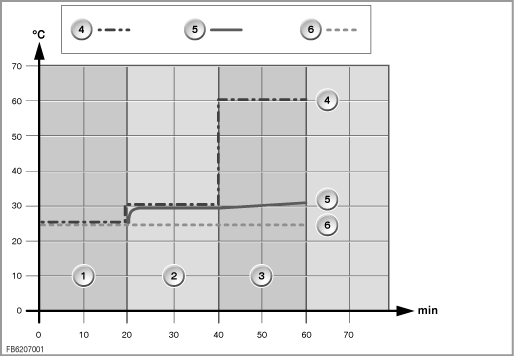
Index |
Explanation |
Index |
Explanation |
|---|---|---|---|
1 |
Motorway driving, 20 minutes, driving speed greater than 80 km/h |
2 |
City traffic, 20 minutes, driving speed greater than 40 km/h |
3 |
Traffic jam, 20 minutes, driving speed |
4 |
Measured value of the outdoor temperature sensor |
5 |
Outside temperature display in the instrument cluster |
6 |
Real outside temperature |
Brightness control
The instrument cluster is illuminated at light ON. A phototransistor is installed in the instrument cluster to calculate the necessary brightness (display, indicator and warning lights, scales, needles).
The brightness value calculated in the instrument cluster is output on the bus system (e.g. for the Central Information Display). Dimming can be set individually using the dimming wheel on the light switch. When the vehicle lighting is switched on, these individual settings and the phototransistor are used to control the dimming. When the vehicle lighting is switched off, the dimming is only controlled by the phototransistor (display brightness according to ambient light).
Set speed of the cruise control
The set speed of the cruise control is transferred from the steering column switch cluster (SZL) on the bus system. The set speed is transferred and displayed with a resolution of 1 km/h. The set speed is indicated by a 2-colour marking (pointer):
- GREEN: Cruise control active
- Orange: Cruise control not active
Notes for Service department
General information
Test functions of the instrument cluster
The test functions are displayed in the TFT display of the instrument cluster. The test functions are used in service to check the encoding. The test functions are also an aid to troubleshooting without the BMW diagnosis system.
Starting the test functions
- Terminal R On or terminal 15 On
- Press the reset button in the instrument cluster for 15 seconds
The test functions can also be started in this way: pressing the reset button and simultaneously switching on terminal R.
Locking and unlocking the test functions (test function 19)
Only the first two test functions are freely accessible. As of the 3rd test function, all other test functions are locked. Unlocking is only possible using test function 19. The test functions are unlocked by entering the total of the vehicle identification number.
Terminating the test function
- Terminal change
- Press the reset button for longer than 5 seconds
- Starting test function 21
National versions
The instrument cluster is available in various national versions.
No liability can be accepted for printing or other faults. Subject to changes of a technical nature