Automatic climate control (IHKA)
Automatic climate control (IHKA)
The automatic climate control (IHKA) with left-right separation is a water-regulated heating and climate control system.
The following equipment variations are available:
- Automatic climate control in Basis version (IHKA Basis)
The IHKA Basis is an automatic climate control with 2.5-zone control.
That means: Left-right separation for driver's and passenger's side and control in the rear (without left-right separation) - Automatic climate control in High version (IHKA High) with rear automatic climate control (FKA)
The IHKA High with FKA is an automatic climate control with 4-zone control.
In addition to the separate settings for the driver's and passenger's side, the FKA also enables separate settings for the left and right sides in the rear. - Automatic climate control in High version (IHKA High) with rear automatic climate control (FKA) and rear automatic climate control (HKA)
The IHKA High with FKA and HKA is an automatic climate control with 4-zone control.
The HKA with left-right separation means that the air supply and air temperature (only cooling possible) in the rear is additionally regulated via the roof air vent.
The major new features of the automatic climate control (IHKA) are:
- Control panel for IHKA is a unit with the control panel for audio
- Fresh air and recirculated air fan of the climate control positioned in the engine compartment
- Ionizer to prevent bacteria growth in the IHKA
Differences between the climate control systems (F01, F02):
|
IHKA Basic |
IHKA High with FKA |
HKA (only F02) |
|---|---|---|---|
Evaporator temperature sensor |
1 |
1 |
1 |
Heating heat exchanger temperature sensor |
2 |
2 |
--- |
Ventilation temperature sensor, front |
2 |
2 |
--- |
Rear compartment ventilation temperature sensor |
--- |
2 |
--- |
Rear footwell temperature sensor |
--- |
2 |
--- |
Roof air vent temperature sensor |
--- |
--- |
2 |
Refrigerant shut-off valve |
--- |
--- |
2 |
Fresh air flap motor |
1 |
1 |
--- |
Recirculated air flap motor |
1 |
1 |
--- |
Defroster-flap motor |
1 |
1 |
--- |
Footwell flap motor, front |
2 |
2 |
--- |
Front stratifying-flap motor |
2 |
2 |
--- |
Ventilation-flap motor |
2 |
4 |
--- |
Rear compartment flap motor |
1 |
--- |
--- |
Footwell flap motor, rear |
--- |
2 |
--- |
Rear compartment mixing flap motor |
--- |
2 |
--- |
Air-distribution-flap motor HKA |
--- |
--- |
2 |
Mixed-air flap motor HKA |
--- |
--- |
2 |
Stratification controls |
2 |
2 |
--- |
Rear stratification control |
1 |
2 |
--- |
Limit-position switch |
--- |
4 |
--- |
Blower with blower output stage |
1 |
2 |
1 |
Brief description of components
The following components are described for the climate control:
- IHKA control module with integrated control panel
- FKA control module with integrated control panel
- HKA control module and control panel
- Blower with blower output stage
- Ionizer
- Electric auxiliary heater
- Electric auxiliary heater in the climate control
(only vehicles with diesel engines) - Electric auxiliary heater rear left and electric auxiliary heater rear right
(only IHKA High with FKA)
- Electric auxiliary heater in the climate control
- Flap motors
- Stratification controls
- Limit-position switch
- Sensors
- Internal temperature sensor (IHKA and FKA)
- Coolant pressure sensor
- Evaporator temperature sensor (IHKA and HKA)
- Rain-light-solar-condensation sensor
- Sensor for automatic recirculated air control (AUC sensor)
- Heating heat exchanger temperature sensor
- Ventilation temperature sensor
- Rear footwell temperature sensor
- Roof air vent temperature sensor
- Internal temperature sensor (IHKA and FKA)
- Dual water valve
- Refrigerant shut-off valve at front and rear
- A/C compressor
- Condenser with integrated drier flask
- Expansion valve
IHKA control module with integrated control panel
The control panel and control module together form a single component. The control panel of the IHKA forms a unit with the audio control panel.
The IHKA is operated using the operating elements shown in the illustration. The nominal temperature is set on the control panel separately for the driver's and passenger's side. The control module regulates the climate control to the desired temperature. In doing so, the control module picks up the sensor signals and continuously adapts the adjusting values for delivery temperature and blower output. The seat heating and active seat ventilation (if fitted) are also operated using buttons in the control panel.
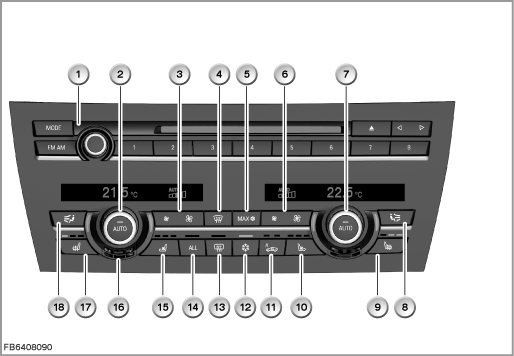
Index |
Explanation |
Index |
Explanation |
|---|---|---|---|
1 |
Audio control panel |
2 |
Temperature selector control, left, with AUTO button |
3 |
Fan button, residual-heat button and button for intensity of the AUTO program on left |
4 |
Defrost button |
5 |
MAX button (for maximum cooling) |
6 |
Fan button, residual-heat button and button for intensity of the AUTO program on right |
7 |
Temperature dial on right with AUTO button |
8 |
Button for manual air distribution, right |
9 |
Seat heating button, right |
10 |
Button for active seat ventilation, right |
11 |
Button for fresh-air mode / automatic air-recirculation mode (AUC) / air-recirculation mode |
12 |
A/C button |
13 |
Heated rear window button |
14 |
ALL button (current settings on the driver's side are applied to the passenger's side and in the rear, left and right) |
15 |
Button for active seat ventilation, left |
16 |
Opening for force-ventilated interior temperature sensor |
17 |
Seat heating button, left |
18 |
Button for manual air distribution, left |
FKA control module with integrated control panel
The control panel and control module together form a single component. The rear automatic climate control (FKA) control panel / control module is fitted in the rear of the center console. The FKA is operated using the operating elements shown in the illustration. The nominal temperature is set on the control panel separately for the driver's and passenger's side, rear. The control module regulates the climate control to the desired temperature. In doing so, the control module picks up the sensor signals and continuously adapts the adjusting values for delivery temperature and blower output. The rear seat heating and rear active seat ventilation (if fitted) are also operated using buttons in the control panel.
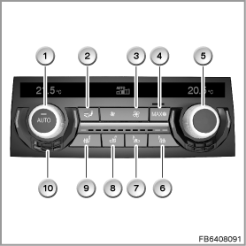
Index |
Explanation |
Index |
Explanation |
|---|---|---|---|
1 |
Temperature selector control, left, with AUTO button |
2 |
Button for manual air distribution |
3 |
Fan button |
4 |
MAX button (for maximum cooling) |
5 |
Temperature selector, right |
6 |
Seat heating button, right |
7 |
Button for active seat ventilation, right |
8 |
Button for active seat ventilation, left |
9 |
Seat heating button, left |
10 |
Opening for force-ventilated interior temperature sensor |
HKA control module and control panel
The control panel and control module are installed separately. The control module of the rear automatic climate control (HKA control module) is installed on the rear climate control.
The HKA control module activates the mixed-air flap motors, the air-distribution-flap motors, the LEDs, as well as the fan of the rear climate control by means of an output stage.
The left-right separation means that the rear climate control has 2 control panels (left-hand control panel on the rear climate control and right-hand control panel on the rear climate control). A control panel is installed each roof air vent.
The control panels regulate the air supply and air temperature (only cooling possible) in the rear via the two roof air vents.
The left-hand control panel on the rear climate control is connected directly via a plug-in connection to the right-hand control panel on the rear climate control. This means that all the settings for the left-hand control panel on the rear climate control are picked up and digitized in the electronics of the right-hand control panel on the rear climate control. The right-hand control panel on the rear climate control sends the signals on the LIN bus to the HKA control module.
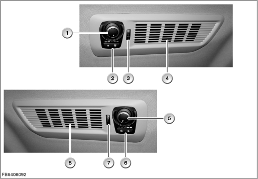
Index |
Explanation |
Index |
Explanation |
|---|---|---|---|
1 |
Temperature dial (only cooling possible) in the right-hand control panel on the rear climate control |
2 |
Button for manual variation of the air flow rate and LEDs to indicate the selected air flow rate on the right |
3 |
Setting dial to change the flow direction on the right |
4 |
Air exit at roof air vent on the right |
5 |
Temperature dial (only cooling possible) in the left-hand control panel on the rear climate control |
6 |
Button for manual variation of the air flow rate and LEDs to indicate the selected air flow rate on the left |
7 |
Setting dial to change the flow direction on the left |
8 |
Air exit at roof air vent on the left |
Blower with blower output stage
The fan consists of the fan motor, the fan wheel, the fan output stage and the housing.
Depending on the equipment variant, the following fans and fan output stages are installed:
- Fan with fan output stage (IHKA)
The fan creates the necessary air-mass flow in the climate control.
At the fan output stage, the control module of the automatic climate control (IHKA control module) specifies the voltage for the fan motor. The specified voltage is output by the IHKA control module as a signal on the LIN bus.
Depending on this control signal, the fan motor is activated by the fan output stage.
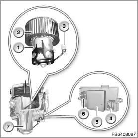
Index |
Explanation |
Index |
Explanation |
|---|---|---|---|
1 |
Blower motor |
2 |
Fan wheel |
3 |
Plug-in connection |
4 |
Plug connection (connection to fan motor) |
5 |
Blower output stage |
6 |
Plug connection (connection to the wiring harness) |
7 |
Fan of the climate control |
|
|
- Rear compartment fan with output stage for the rear compartment fan motor (FKA)
The rear compartment fan is installed in the center console; it generates an additional air-mass flow for the rear climate control.
At the output stage, the control module of the rear automatic climate control (FKA control module) specifies the voltage for the rear compartment fan motor. The specified voltage is output by the FKA control module as a PWM signal (pulse-width modulated signal) to the output stage.
Depending on this control signal, the fan motor is activated by the output stage.
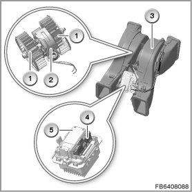
Index |
Explanation |
Index |
Explanation |
|---|---|---|---|
1 |
Fan wheels |
2 |
Rear compartment fan motor |
3 |
Housing |
4 |
Plug-in connection |
5 |
Output stage for rear compartment fan motor |
|
|
- Fan with fan output stage (HKA)
The fan creates the necessary air-mass flow in the rear climate control.
At the fan output stage, the control module of the rear automatic climate control (HKA control module) specifies the voltage for the fan motor. The specified voltage is output by the HKA control module as a signal on the LIN bus.
Depending on this control signal, the fan motor is activated by the fan output stage.
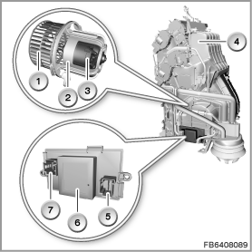
Index |
Explanation |
Index |
Explanation |
|---|---|---|---|
1 |
Fan wheel |
2 |
Blower motor |
3 |
Motor bracket |
4 |
Rear climate control |
5 |
Plug connection (connection to fan motor) |
6 |
Blower output stage |
7 |
Plug connection (connection to the wiring harness) |
|
|
Ionizer
The ionizer treats the air upstream of the evaporator.
The ionizer contains a ceramic plate covered with toughened glass. Electrical conductors are attached to the front and back. An AC voltage of approx. 3 kV is applied to the electrode by the control electronics circuit.
The application of a device-internal high voltage leads to partial ionization of the air. The reaction generates hydrogen peroxide. The hydrogen peroxide produces a chemical reaction that removes bacteria for the most part from the evaporator and other components of the automatic climate control.
The ionizer is controlled depending on the automatic program as well as the operating state of the vehicle. The IHKA control module activates the ionizer by means of a pulse-width modulated signal (PWM signal).
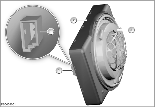
Index |
Explanation |
Index |
Explanation |
|---|---|---|---|
1 |
3-pin plug-in connection |
2 |
Housing |
3 |
Ionizer |
|
|
Electric auxiliary heater
The electric auxiliary heater using the PTC principle (resistance with positive temperature coefficient) heats the air flow to adjust the temperature of the vehicle interior. The electric auxiliary heater accelerates heating of the vehicle interior, particularly at low outside temperatures and during the cold starting phase.
The electric auxiliary heater operates using the same principle as an electric radiator.
The heating elements in the electric auxiliary heater are cold conductors. The heating elements consist of individual ceramic semiconductor resistors.
The resistance of the heating element has a positive temperature coefficient as of a certain temperature. That means: The warmer the heating elements become, the higher their resistance. When the electric auxiliary heater is switched on, a high level of current flows. With increasing heat, this level of current falls. This limits the maximum current consumption. These electrical characteristics of the resistors enable a temperature of approx. 120 °C in the area of the heating elements that presents no problem for the climate control. This ”physical” over-temperature protection is ensured even in the event of a blower failure.
The following electric auxiliary heaters are installed:
- Electric auxiliary heater in the climate control (only vehicles with diesel engines)
The electric auxiliary heater is a separate component and is installed in the climate control. The electric auxiliary heater is activated by the control module of the automatic climate control (IHKA control module). Depending on different signals (e.g. temperature signal from the rear footwell temperature sensor, signals from energy management), a percentage power request for the electric auxiliary heater is generated in the IHKA control module and sent on the LIN bus
The maximum electrical power output of the electric auxiliary heater depends on the resources of the vehicle network. As a general principle, only the surplus power output of the alternator is available to the electric auxiliary heater.
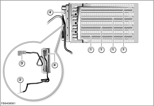
Index |
Explanation |
Index |
Explanation |
|---|---|---|---|
1 |
Heating element |
2 |
Connection of the load ground (for heating elements and electronics) |
3 |
Connection of power supply |
4 |
Connection for the LIN bus |
- Electric auxiliary heater in rear left and rear right (only IHKA High with FKA)
The electric auxiliary heaters are part of the rear automatic climate control (FKA) with left-right separation. An electric auxiliary heater is fitted in each footwell ventilation duct.
Depending on different signals (e.g. temperature signal from the rear footwell temperature sensor, signals from energy management), a percentage power request for the electric auxiliary heater is generated in the FKA control module and sent by means of a pulse-width modulated signal (PWM signal).
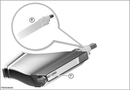
Index |
Explanation |
Index |
Explanation |
|---|---|---|---|
1 |
Footwell temperature sensor |
2 |
Electric auxiliary heater, rear left |
Flap motors
The flap motors are activated and supplied with voltage and ground across the LIN bus by the corresponding control module (IHKA control module, HKA control module). In the idle state, the control module switches the power supply off.
The flap motor is fitted with an integrated circuit. This circuit controls the coil of the flap motor. The circuit is bus- and diagnosis-compatible.
After activation of the flap motor, the integrated circuit sends a position message (actual position) to the control module.
The flap motors communicate across the LIN bus with the HKA control module. The flap motors are switched in series on the LIN bus.
Each flap motor is assigned a certain address. The address determines what function the flap motor assumes in the composite system. This address tells e.g. the rear right footwell-flap motor that messages are being addressed to it (e.g. 'open flap'). This address tells e.g. the IHKA control module which flap motor has sent it a fault message.
Stratification controls
The selected potentiometer setting is implemented on the flap position of each flap motor.
Limit-position switch
With the help of the limit-position switch, the ventilation flap picks up the following positions:
- Ventilation flap open (contact in the limit-position switch closed)
- Ventilation flap closed (contact in the limit-position switch open)
The limit-position switches are switched on and off mechanically via eccentric washers. The IHKA control module evaluates the information from the limit-position switch.
If the ventilation flap is closed manually, the IHKA control module activates the corresponding ventilation-flap motor in the automatic climate control (IHKA) on the basis of the signals from the limit-position switch. This completely blocks the air flow to the air vents in the ventilation grille.
Sensors
The following sensors are installed in the climate control:
- Internal temperature sensor
The IHKA and FKA control panel both contain a force-ventilated internal temperature sensor with internal temperature sensor fan.
The internal temperature sensor measures the air temperature that the integrated internal temperature sensor fan extracts from the vehicle interior. - Refrigerant pressure sensor
The refrigerant pressure sensor is located in the pressure line between the condenser and the evaporator. Depending on the sensor signal, the output of the A/C compressor is reduced via the control module of the automatic climate control (IHKA control module) if the refrigerant pressure is too high. The junction box supplies the coolant pressure sensor with voltage. The data are evaluated in the junction box electronics (JBE). The prepared data is sent across the body CAN (K-CAN) to the IHKA control module. - Evaporator temperature sensor
The evaporator temperature sensor picks up the outlet temperature of the cooled air at the evaporator to prevent freezing of the evaporator.
The evaporator temperature sensor of the automatic climate control (IHKA) is directly connected to the IHKA control module.
The evaporator temperature sensor of the rear climate control is directly connected to the HKA control module (”HKA” stands for ”rear automatic climate control”). - Rain-light-solar-condensation sensor
The solar sensor and condensation sensor are parts of the rain-light-solar-condensation sensor.
The solar sensor enables the automatic climate control (IHKA) to take account of solar radiation.
The solar sensor measures the sunlight on the vehicle. Here, the solar radiation on the driver's side as well as on the passenger's side are registered separately.
Adaptation to the solar radiation is only active in the automatic program.
The condensation sensor enables the IHKA to detect window condensation at an early stage, even before the driver can detect it. Countermeasures (program to prevent window condensation) can be initiated at an early stage without the driver needing to intervene.
The condensation sensor provides the following information:- Temperature on inside of the windscreen
- Atmospheric humidity on inside of the windscreen
The junction box electronics (JBE) adopts the signals into the corresponding CAN message and sends them. The IHKA control module is equipment attached to the bus on the K-CAN.
If the rain and/or condensation sensor system fails, a fault memory entry is made in the junction box electronics (JBE). - Temperature on inside of the windscreen
- Sensor for automatic recirculated air control (AUC sensor)
The AUC sensor is a metal oxide sensor. This sensor is highly sensitive to various smells and pollutants that are typical of traffic.
The AUC sensor is fitted on the micro-filter compartment. The AUC sensor evaluates the concentration of carbon monoxide and nitrogen oxides in the intake fresh air.
The AUC sensor converts the detected air quality (also referred as air grade) into an electrical signal. To simplify processing of the information, the air quality in 10 levels:- Level 0 to Level 10 (clean to severely contaminated)
If the AUC sensor measures an excessive emission value, the control module of the automatic climate control (IHKA control module) switches to the recirculated-air mode (precondition: IHKA in the automatic mode). - Level 0 to Level 10 (clean to severely contaminated)
- Heating heat exchanger temperature sensor
Two sensors are installed in the automatic climate control (IHKA), as the delivery temperature at the heat exchanger for the heating system is registered separately for the driver's and passenger's side. The sensors are directly connected to the IHKA control module. - Ventilation temperature sensor
Two sensors are installed in the automatic climate control (IHKA), as the delivery temperature at the middle ventilation flap is registered separately for the driver's and passenger's side.
One sensor is installed in the footwell vent outlet in the center console (no left-right separation in the rear).
The three sensors are connected to the IHKA control module.
The left-right separation means that 2 sensors are installed (on the right-hand and left-hand footwell vent outlets) in the footwell vent outlet in the center console IHKA High with rear automatic climate control (FKA). The sensors are connected to the FKA control module.
The FKA control module evaluates the signals from the sensors. The signal is sent as a message on the CAN bus. The IHKA control module uses this message to regulate the corresponding flap motor. - Rear footwell temperature sensor
The left-right separation means that 2 sensors are installed on the rear automatic climate control (FKA). One sensor is attached to each of the left and right footwell air vents. The sensors are directly connected to the FKA control module.
The FKA control module evaluates the signals from the sensors. The signal is sent as a message on the CAN bus. The IHKA control module uses this message to regulate the corresponding rear footwell-flap motor. - Roof air vent temperature sensor
The two roof air vents are only installed in conjunction with the rear climate control. The left-right separation means that a roof air vent temperature sensor is installed in each roof air vent.
The signals of the 2 sensors are picked up and digitized in the control panel of the rear climate control on the right. The control panel sends the signals on the LIN bus to the HKA control module. The HKA control module evaluates this information and activates the air-distribution-flap motors and mixed-air flap motors.
Dual water valve
The dual water valve is an electromagnetic valve that meters the coolant flow volume to the heat exchanger for the heating system with left-right separation in line with requirements. This determines the air temperature used for heating the vehicle interior. The junction box electronics (JBE) control the dual water valve.
Refrigerant shut-off valve at front and rear
The rear automatic climate control (HKA) is connected to the chiller circuit of the automatic climate control (IHKA) and is supplied from the same A/C compressor. The two refrigerant circuits are separated by 2 refrigerant shut-off valves (front and rear) which are only fitted together with the HKA.
The front refrigerant shut-off valve is integrated in the expansion valve of the IHKA and it blocks the pressure line to the front evaporator.
The rear refrigerant shut-off valve is integrated in the expansion valve of the HKA and it blocks the pressure line to the rear evaporator.
The connection and control operation of the HKA for the refrigerant circuit of the IHKA is designed in such a way that independent operation is possible. If both systems are in operation, clocking the 2 refrigerant shut-off valves can regulate both systems independently of one another. However, at least one refrigerant shut-off valve must always be opened.
The HKA control module activates the refrigerant shut-off valves (front and rear). Without current, the refrigerant shut-off valves are closed.
A/C compressor
The A/C compressor compresses the refrigerant taken in by the evaporator. The refrigerant is pressed towards the condenser.
The A/C compressor driven by the engine by means of a belt drive. The A/C compressor is switched on and off via a magnetic clutch.
Stepless power control is possible in the A/C compressor. Within the A/C compressor, the delivery volume and thus the pressure in the refrigerant circuit is generated by pistons. The piston stroke is controlled by a swash plate. The electric control valve on the A/C compressor influences the balance of forces on the swash plate and thus the adjustment of the displacement.
The junction box electronics (JBE) control the control valve with a clocked voltage. The IHKA control module specifies the activation.
To reduce the load, only the cooling output that is required at a specific moment is generated.
Condenser with integrated drier flask
In the condenser, gaseous refrigerant is converted into liquid refrigerant. In the integrated downstream drier flask, any water present in the refrigerant circuit is bound.
Expansion valve
The expansion valve controls the injection quantity into the evaporator. Only as much liquid refrigerant enters the evaporator as the evaporator is able to completely evaporate. Drops of liquid that have not been evaporated would cause damage in the A/C compressor.
System functions
The following system functions are described for the automatic climate control IHKA rear automatic climate control:
Functional networking
- IHKA Basis and IHKA High
The following illustration shows the functional networking for the automatic climate control in the Basis version (IHKA Basis) and High version (IHKA High).
The rear automatic climate control (FKA) is part of the IHKA High, but for reasons of space it is shown separately.
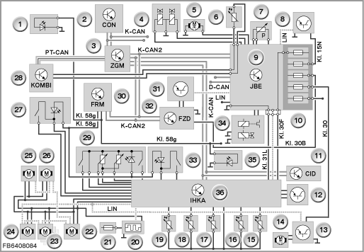
Index |
Explanation |
Index |
Explanation |
|---|---|---|---|
1 |
Locating lights in the ventilation grille, B-pillar on the left |
2 |
Controller (CON) |
3 |
Central gateway module (ZGM) |
4 |
Dual water valve |
5 |
Additional coolant pump |
6 |
Outside temperature sensor |
7 |
Coolant pressure sensor |
8 |
AUC sensor |
9 |
Junction box electronics (JBE) |
10 |
Power distributor in junction box |
11 |
Central Information Display (CID) |
12 |
Ionizer |
13 |
Blower output stage |
14 |
Blower motor |
15 |
Ventilation temperature sensor, front right |
16 |
Heating heat exchanger temperature sensor, right |
17 |
Evaporator temperature sensor |
18 |
Left heating heat exchanger temperature sensor |
19 |
Ventilation temperature sensor, front left |
20 |
Electric auxiliary heater |
21 |
Distribution box in the engine compartment |
22 |
IHKA Basis: ventilation-flap motor on the left* IHKA High with FKA: |
23 |
Other flap motors* |
24 |
Footwell flap motor, front left* |
25 |
Fresh-air-flap motor* |
26 |
Recirculated-air-flap motor* |
27 |
Ventilation grille at the front left with locating lights. Limit-position switch only for IHKA High with FKA |
28 |
Instrument cluster (KOMBI) |
29 |
Front center ventilation grille with locating lights and 2 stratification controls. Limit-position switches (2) only for IHKA High with FKA |
30 |
Footwell module (FRM) |
31 |
Rain-light-solar-condensation sensor |
32 |
Roof control panel (FZD) |
33 |
Ventilation grille at the front right with locating lights. Limit-position switch only for IHKA High with FKA |
34 |
A/C compressor with magnetic coupling and control valve |
35 |
Locating lights in the ventilation grille, B-pillar on the right |
36 |
IHKA control module |
D-CAN |
Diagnosis-on CAN |
K CAN |
Body CAN |
K-CAN2 |
Body CAN2 |
Terminal 15N |
Switch off terminal 15N with after-run |
Terminal 30 |
Terminal 30 permanent positive |
Terminal 30B |
Terminal 30B, base operation |
Kl. 30F |
Shutdown of terminal 30F in event of failure |
Terminal 31L |
Terminal 31L, load earth |
Terminal 58g |
Terminal 58g, locating lamp |
LIN |
LIN bus |
PT-CAN |
Powertrain CAN |
|
|
* The stepper motors are switched in series on the LIN bus. |
|||
- Rear automatic climate control (FKA)
The following illustration shows the functional networking for the rear automatic climate control (FKA).
The rear automatic climate control (FKA) is part of the IHKA High, but for reasons of space it is shown separately.
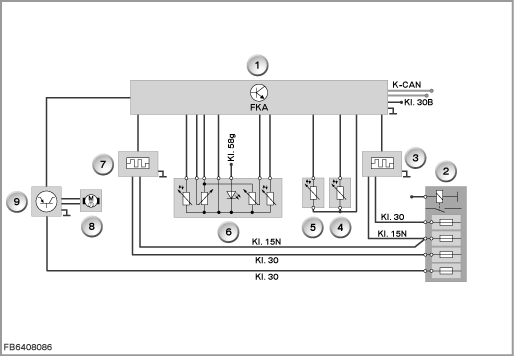
Index |
Explanation |
Index |
Explanation |
|---|---|---|---|
1 |
FKA control module |
2 |
Rear distribution box |
3 |
Electric auxiliary heater, rear right |
4 |
Footwell temperature sensor, rear right |
5 |
Footwell temperature sensor, rear left |
6 |
Rear ventilation grille with locating lights, 2 stratification controls and 2 rear ventilation temperature sensors |
7 |
Electric auxiliary heater, rear left |
8 |
Rear compartment fan motor |
9 |
Output stage for rear compartment fan motor |
K CAN |
Body CAN |
Terminal 15N |
Switch off terminal 15N with after-run |
Terminal 30 |
Terminal 30 permanent positive |
Terminal 30B |
Terminal 30B, base operation |
Terminal 58g |
Terminal 58g locating lights |
- Rear automatic climate control (HKA)
The following illustration shows the functional networking for the rear automatic climate control (HKA).
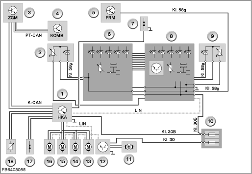
Index |
Explanation |
Index |
Explanation |
|---|---|---|---|
1 |
HKA control module |
2 |
Roof air vent on the left with locating lights and temperature sensor |
3 |
Central gateway module (ZGM) |
4 |
Instrument cluster (KOMBI) |
5 |
Footwell module (FRM) |
6 |
Left-hand control panel on the rear climate control with temperature dial, button for manual variation of the air flow rate and LEDs to indicate the selected air flow rate |
7 |
Refrigerant shut-off valve, front |
8 |
Right-hand control panel on the rear climate control with temperature dial, button for manual variation of the air flow rate, LEDs to indicate the selected air flow rate and electronic module |
9 |
Roof air vent on the right with locating lights and temperature sensor |
10 |
Rear distribution box |
11 |
Fan motor for rear climate control |
12 |
Fan output stage for rear climate control |
13 |
Right-hand air-distribution-flap motor in the rear climate control* |
14 |
Left-hand air-distribution-flap motor in the rear climate control* |
15 |
Right-hand mixed-air flap motor in the rear climate control* |
16 |
Left-hand mixed-air flap motor in the rear climate control* |
17 |
Rear refrigerant shut-off valve |
18 |
Evaporator temperature sensor for rear climate control |
K CAN |
Body CAN |
Terminal 30 |
Terminal 30 permanent positive |
Terminal 30B |
Terminal 30B, base operation |
Terminal 58g |
Terminal 58g, locating lamp |
LIN |
LIN bus |
|
|
* The stepper motors are switched in series on the LIN bus. |
|||
Notes for Service department
General information
Running in the A/C compressor
After replacement of an A/C compressor or refilling the refrigerant circuit, the A/C compressor must be run in. Running in is required to ensure lubrication (oil distribution). Running in can only be carried out using the BMW diagnosis system.
For this running in, the A/C compressor must be operated within the specified engine speed range. Here, the amount of oil filled by the manufacturer mixes evenly with the liquefied refrigerant.
If the engine speed exceeds the specified engine speed range, running in is cancelled automatically. The running-in procedure must then be repeated in its entirety.
Encoding the rain-light-solar-condensation sensor
Coding of the rain-light-solar-condensation sensor is required after replacement of the windscreen or replacement of a rain-light-solar-condensation sensor.
Coding of the climate control
When coding the vehicle-specific data, the following details (among others) are taken into account:
- Engine type
(diesel or spark-ignition) - Version of the climate control
(IHKA Basis or IHKA High with FKA or IHKA High with FKA and HKA)
If, for example, an HKA is installed, the IHKA must be encoded to ”HKA is fitted” (IHKA control module is the master controller; the HKA control module is a slave). Otherwise the built-in refrigerant shut-off valves (front and rear) remain closed and have no function.
No liability can be accepted for printing or other faults. Subject to changes of a technical nature