Car Information Computer
Car Information Computer
The Car Information Computer (CIC) is an enhancement of the Car Communication Computer (CCC). The Car Information Computer will be deployed for the first time as of 03/2008 in a special model series in the E60 and E61. Later, the CIC will also be used in the other model series.
The Car Information Computer is the head unit in the MOST framework.
The essential new features for the CIC are:
- Extended functions for existing systems, e.g. navigation (see also Owner's Manual)
- Additional functions, e.g. central database for address data
- Additional hardware, e.g. hard disk (40 GB) or USB port
- Changed hardware e.g.:
- LVDS data line to the Central Information Display (CID) as two-wire connection
- 1 Drive for DVD and CD
- Operating unit for audio, including favourite buttons, one unit with operating unit for IHKA
- LVDS data line to the Central Information Display (CID) as two-wire connection
- Changed display and operating concept for iDrive via:
- New layout of the user interface on the CID
- New controller with 7 fixed selector buttons
- New layout of the user interface on the CID
- Reduction of the virtual control modules in the CIC
Changes to the software and hardware have made it necessary to extend the diagnosis for the Car Information Computer accordingly.
Brief description of components
The following components are described:
- Car Information Computer
- Central Information Display with LVDS interface
- Controller
- Rear controller with Rear Seat Entertainment
- USB port
Car Information Computer
The Car Information Computer (CIC) has 8 free programmable favourite buttons.
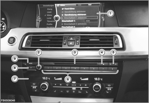
Index |
Explanation |
Index |
Explanation |
|---|---|---|---|
1 |
Central Information Display (CID) |
2 |
Rotary push button |
3 |
Drive of the CIC |
4 |
Eject button for DVD and CD |
5 |
Seek tuning button, backwards and forwards |
6 |
Favourite buttons |
7 |
IHKA operating unit |
8 |
Button for traffic announcements (TP = Traffic Programme), depending on the country |
9 |
MODE button (changeover of audio source) |
|
|
In principle, the structure of the CIC corresponds to that of a personal computer. In a similar way to a PC, the CIC contains:
- Processor
- Main memory
- Hard disk
- Fan
The extended range of functions means that the plug connections on the back of the Car Information Computer have also changed.
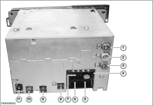
Index |
Explanation |
Index |
Explanation |
|---|---|---|---|
1 |
LVDS interface (LVDS = Low Voltage Differential Signalling) |
2 |
USB port |
3 |
Ethernet connection |
4 |
MOST interface |
5 |
12-pin connector, telephone, AUX-In |
6 |
12-pin connector, video signals |
7 |
16-pin connector, K-CAN, wheel-speed signals |
8 |
GPS antenna |
9 |
DAB antenna (L-Band) |
10 |
DAB antenna (III Band) |
11 |
AM antenna and FM antenna |
|
|
The following other components are integrated in the Car Information Computer (CIC):
- Navigation computer, HIP module as well as yaw rate sensor
The HIP module receives e.g. the following data:
date, time and locations of the GPS antennas. The navigation system uses the data from the HIP module to calculate the vehicle position.
The yaw rate sensor delivers the data regarding a change in driving direction. This data is required for more accurate location determination, as the satellite signals cannot be received everywhere (e.g. tunnels, underground car parks). - Three-way tuner: FM, AM and TMC
- DAB tuner
- Audio System Controller
- Gateway between MOST and CAN
The operating unit for audio with the favourite buttons is not connected directly to the CIC. The operating unit is integrated in the operating unit for the IHKA. The electrical connection is by means of a ribbon cable leading to the IHKA control module. The IHKA sends the signals in messages on the K-CAN.
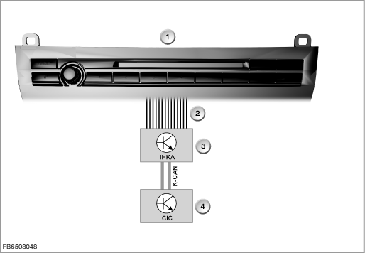
Index |
Explanation |
Index |
Explanation |
|---|---|---|---|
1 |
Audio operating unit |
2 |
Ribbon cable, 14-pin |
3 |
Automatic climate control (IHKA) |
4 |
Car Information Computer (CIC) |
K CAN |
Body CAN |
|
|
Central Information Display with LVDS interface
The Central Information Display (CID) measures 10.2 inches. The resolution is 1280 x 480 pixels. This increases the contrast and improves legibility.
The display and operating concept for iDrive has changed. Selection of the start menus is arranged in linear form in lists (no longer star-shaped). The submenus are also placed horizontally one above the other.
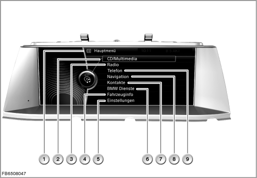
Index |
Explanation |
Index |
Explanation |
|---|---|---|---|
1 |
Start menu |
2 |
CD / multimedia |
3 |
Radio |
4 |
Vehicle information |
5 |
Settings |
6 |
BMW center |
7 |
Contacts |
8 |
Navigation |
9 |
Telephone |
|
|
With introduction of the Car Information Computer, the LVDS data line is a two-wire connection. This new LVDS data line has the following advantages:
- Higher data transfer rate
- No difference in the signal runtime between the individual lines
- Simpler and lower-cost technology
A 4-wire, screened cable is used for the two-wire connection. This solution involves lower costs, even though one of the 4 lines is not used actively.
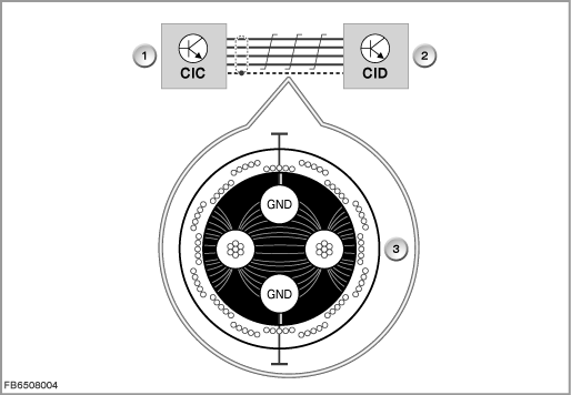
Index |
Explanation |
Index |
Explanation |
|---|---|---|---|
1 |
Car Information Computer (CIC) |
2 |
Central Information Display (CID) |
3 |
Cross-section drawing of LVDS data line |
|
|
To prevent EMV faults, the unused line is also grounded. The capacitive disruptive influences of the signals are diverted to ground. Furthermore, grounded lines form a defined potential and cannot have the same effect as antennas.
Note! Orange-coloured display in the event of a fault.
Troubleshooting is made easier by a separate display.
With the following faults, the display turns orange:
- Defective picture signal from the head unit
- Interrupted LVDS data line
- Defective plug-in connection
Controller
There are 7 fixed selector buttons arranged around the new controller. These selector buttons now enable selection of half of all the submenus.
The following submenus can still be selected only from the start menu:
- Contacts
- BMW center
- Vehicle information
- Settings
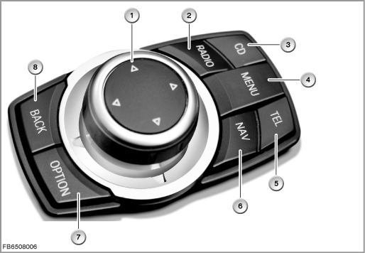
Index |
Explanation |
Index |
Explanation |
|---|---|---|---|
1 |
Controller (CON) |
2 |
Radio selector button |
3 |
CD / multimedia selector button |
4 |
Start menu selector button |
5 |
Telephone selector button |
6 |
Navigation selector button |
7 |
”Option” selector button |
8 |
”Back” selector button |
When pressed, the ”Back” button returns the user to the last screen displayed. The ”Option” button enables other settings in the last selected submenu.
The selector buttons are used now instead of pushing the controller for a longer period in a certain direction.
A small switch block is electrically connected at the controller. Depending on the options fitted, the switch block contains the controls for the Park Distance Control (PDC = parking aid) as well as for the bumper camera. The signals are placed by the controller (CON) on the K-CAN.
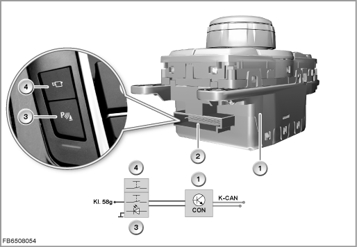
Index |
Explanation |
Index |
Explanation |
|---|---|---|---|
1 |
Controller (CON) |
2 |
10-pin plug-in connection |
3 |
Control button for Park Distance Control (parking aid) or rear view camera |
4 |
Control for bumper camera |
Rear compartment controller
In vehicles with Rear Seat Entertainment, a rear controller is connected on the K-CAN. The rear controller is identical to the front controller.
Two folding rear displays with 800 x 480 pixels as well as an infrared transmitter unit are deployed in the rear (optional extra 6FG or optional extra 6FH). The rear displays are integrated in the backrests of the front seats. On both versions, the control module (RSE) is integrated for the first time in the MOST bus. The Car Information Computer (CIC) serves as the master control module for the MOST bus.
The rear displays are also connected on the K-CAN.
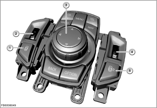
Index |
Explanation |
Index |
Explanation |
|---|---|---|---|
1 |
Selector button, left |
2 |
Knurled wheel for volume, left |
3 |
Rear controller (FCON) |
4 |
Selector button, left |
5 |
Knurled wheel for volume, right |
|
|
When pressed, the ”Back” button returns the user to the last screen displayed. The ”Option” button enables other settings in the last selected submenu.
The selector buttons are used now instead of pushing the controller for a longer period in a certain direction.
USB port
There is a USB port in the glove box. The data of a USB stick (music files in the format MP3, WMA or AAC) can be imported via this USB port.
Imported USB music data is stored in a music collection. The file folders are stored with USB 1, USB 2 on the hard disk.
Note! No import is possible via the USB audio interface.
An import via the USB audio interface (optional extra 6FL, ULF-SBX-H) in the centre console is not possible. This interface is still only intended for playback of external audio sources.
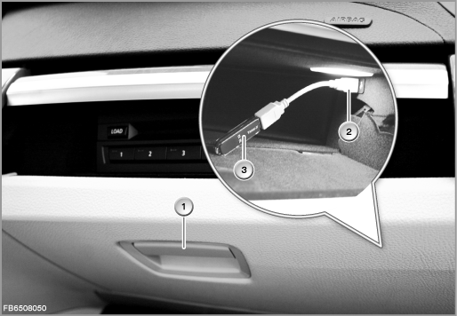
Index |
Explanation |
Index |
Explanation |
|---|---|---|---|
1 |
Glove compartment |
2 |
USB port |
3 |
USB stick |
|
|
USB sticks with the standard USB 1.1 are supported. However, the standard USB 2.0 (= high speed) is recommended.
If the USB stick has been partitioned, the files must be located on the first partition. This is the only way these files are recognized and used. The USB port supplies the USB stick with a maximum of 500 mA.
USB hard disks, USB hubs and USB memory card readers with a number of bays cannot be read at the USB interface.
System functions
The following system functions are described:
- Car Information Computer composite system
- Additional functions on the Car Information Computer
- Personalization of settings
Car Information Computer composite system
The following illustration shows the composite system for the Car Information Computer (CIC).
The CIC is supplied with voltage via terminal 30g-f.
In the Japanese version, the antennas for VICS (Vehicle Information Communications System) and ETC (Electronic Toll Collect) are also connected to the CIC.
With the Navigation optional extra, the GPS antenna is connected to the CIC.
On vehicles without a telephone, the vehicle microphone (voice control) is also connected to the CIC.
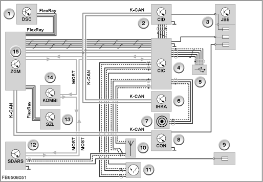
Index |
Explanation |
Index |
Explanation |
|---|---|---|---|
1 |
DSC (Dynamic Stability Control) |
2 |
Central Information Display (CID) |
3 |
Junction box electronics (JBE) |
4 |
Car Information Computer (CIC), shown without speaker connections |
5 |
USB port in the glove box |
6 |
Automatic climate control (IHKA) with operating unit |
7 |
AUX-In connection |
8 |
Controller (CON) |
9 |
Rear distribution box |
10 |
Roof-mounted antenna |
11 |
Antenna diversity |
12 |
Satellite tuner (SDARS) |
13 |
Steering Column Switch Cluster (SZL) |
14 |
Instrument cluster (KOMBI) |
15 |
Central gateway module (ZGM) |
|
|
Note! Special feature of programming
The diagnosis plug is connected to the CIC via Ethernet (5 lines). The central gateway module (ZGM) is located in between. The CIC is programmed via Ethernet.
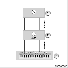
Index |
Explanation |
Index |
Explanation |
|---|---|---|---|
1 |
Car Information Computer (CIC) |
2 |
Central gateway module (ZGM) |
3 |
Diagnosis plug |
|
|
There is no longer a MOST direct access point.
Additional functions on the Car Information Computer
Note! Please comply with instructions in Owner's Manual.
The new functions provided by the CIC are described in detail in the Owner's Manual.
To provide an overview, the new functions are summarized briefly.
- DVD drive functions
The Car Information Computer is equipped with a DVD drive (ROM). The drive permits playback of the following media:- Audio CD (CD Digital Audio)
- Audio CD with files in the format MP3, WMA or AAC
- Audio DVD (only stereo track if on the data medium)
- Audio DVD with files in the format MP3, WMA or AAC
- Video DVD
This means the drive is available for playback of audio and video sources. - Audio CD (CD Digital Audio)
- Hard disk functions
For the first time, a hard disk for storage of application software and data is deployed in the head unit of a BMW vehicle. This enables the implementation of complex graphics: e.g. 3D altitude models for navigation.
Furthermore, a database with music tracks has been implemented (music collection). This provides the possibility to convert, store and play music tracks of the customer. Three languages are stored on the hard disk for the voice recognition system.
For the additional functions, the approx. 40 GB of the hard disk are divided as follows:- 25 GB navigation system
- 8 GB music collection
- 4 GB database audio (music search, Gracenote)
- 2 GB system administration
- 0.5 GB voice control
- 0.5 GB interactive Owner's Manual
- 25 GB navigation system
Personalization of settings
For BMW vehicles, the personalization of functions is known as a Personal Profile. Here, individual settings are stored in the vehicle on a key-dependent basis. The settings are called up again on unlocking the vehicle.
With application of the Car Information Computer (CIC) as of F01, Mobile Profile is possible.
Definition of Mobile Profile:
Importing the personal settings into another vehicle.
With the Mobile Profile, the Personal Profile of the user can be transferred across the following interfaces:
- External USB memory
- Online via the BMW Portal
Subsequently, the Personal Profile can be imported into another BMW vehicle.
The Car Access System (CAS) is the master control module for the personalization.
The following profile numbers are possible:
Profile number |
Definition |
|---|---|
0 |
Profile 0 |
1 |
Profile 1 |
2 |
Profile 2 |
15 |
Guest profile |
20 |
Invalid profile |
A service function in the BMW diagnosis system can be used to reset the settings of the Personal Profile.
Moreover, a service function can be used to read out and change the profile numbers in the CAS.
Notes for Service department
General information
Important! Pay attention to electrostatic discharge.
When working on the CIC, particular attention must be paid to electrostatic discharge (ESD).
When working on electronic components of the CIC, comply with the following rules:
- The work must be executed on a conductive and grounded workbench. The additional special tool 12 7 192 is also used.
- The earthing cable is to be connected to a safe earthing point (water pipe, heating pipe, power socket earthing).
- First of all, the person doing the work puts on the wrist collar to achieve a discharge before taking parts out of the packaging.
- The electronic components are placed on the antistatic mat and also connected to the earthing cable.
Note! Components that can be replaced.
On the Car Information Computer (CIC), fewer components can be replaced that on the Car Communication Computer (CCC).
The following components can be replaced:
- Complete CIC
- Hard disk
- DVD drive
- Complete operating unit for IHKA and audio
Note! Note data backup.
The ”Options” submenu provides the possibility to back up the complete music collection. Here, the data must be stored on a USB stick. Use a USB stick with a memory capacity of 8 GB. This function is already displayed in 03/2008, but is only enabled from 09/2008 onwards.
A data backup is only possible if the hard disk of the CIC has not been damaged and the interfaces to the CIC are still working perfectly. No recovery of music data has been agreed with the manufacturer of the CIC (Harman/Becker). This means that without a data backup the music files are irrevocably lost.
Diagnosis instructions
Note! Use the service function.
A service function in the BMW diagnosis system can be used to reset the settings of the Personal Profile.
Path: Service functions > Body > Car Information Computer > Restore delivery status
Diagnosis is available on the BMW diagnosis system for the following tasks:
- Complete CIC
- Navigation system
- Connected devices
- Voltage supply
- Quality check (audio test CD)
- Speaker
- Antennas
- MOST
- Video system
If ”noticeable symptoms” is selected, a fault pattern catalogue is available.
No liability can be accepted for printing or other faults. Subject to changes of a technical nature