parking aid
Park Distance Control (PDC) is an optional extra. Park Distance Control (i.e.: parking aid) assists the driver when he is parking and manoeuvring in tight spaces. This means that even small parking spaces can be used. At the same time, the amount of parking damage is reduced. The PDC runs a distance measurement in relation to objects in the pickup range by means of ultrasonic sensors.
Slow approaches to an object in front of or behind the vehicle are indicated by:
- Acoustic warnings
- Visual warning
Note: PDC is not an independent control module.
The PDC is integrated in the junction box electronics (JBE), but it has its own control module address and diagnosis address.
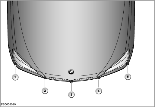
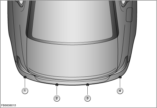
New is the arrangement of the ultrasonic sensors (on the F01/F02). There 5 ultrasonic sensors installed in the front bumper. There 4 ultrasonic sensors in the rear bumper.
Arrangement of the front ultrasonic sensors
Index |
Explanation |
Index |
Explanation |
|---|---|---|---|
1 |
Ultrasonic sensor, front right side |
2 |
Front outer right ultrasonic sensor |
3 |
Front centre ultrasonic sensor |
4 |
Front outer left ultrasonic sensor |
5 |
Ultrasonic sensor, front left side |
|
|
Arrangement of the rear ultrasonic sensors
Index |
Explanation |
Index |
Explanation |
|---|---|---|---|
1 |
Rear outer left ultrasonic sensor |
2 |
Ultrasonic sensor, rear centre left |
3 |
Ultrasonic sensor, rear centre right |
4 |
Rear outer right ultrasonic sensor |
Brief description of components
The following components are described for the parking aid:
Ultrasonic sensor
Combined transmit and receive mode
In the combined transmit and receive mode, the ultrasonic sensors first of all transmit a package of ultrasonic impulses in succession. Subsequently, the ultrasonic sensors pick up the echo impulse that is reflected by an object in the pickup range. This echo impulse is amplified in the ultrasonic sensor and forwarded as a digital signal to the junction box electronics (JBE). The JBE uses the runtime of the echo impulse to calculate the distance to the object.
Receive mode
In the receive mode, an ultrasonic sensor picks up the echo impulses sent by neighbouring ultrasonic sensors. The JBE can thus evaluate the signals from up to 3 ultrasonic sensors (”trilateration” = the neighbouring sensors also ”listen”). This signal evaluation of a number of ultrasonic sensors is used to calculate the minimum distance between the vehicle and the object.
Index |
Explanation |
Index |
Explanation |
|---|---|---|---|
1 |
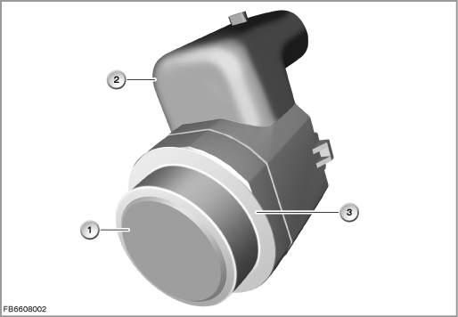
Ultrasonic sensor |
2 |
3-pin plug-in connection |
3 |
Decoupling element |
|
|
All the ultrasonic sensors have their own electronics. The front and rear ultrasonic sensors have a joint power supply and earth contact at the control module.
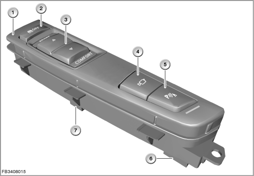
PDC button in the centre console operating unit
The PDC button switches the parking aid on or off (see Owner's Manual). When the PDC is switched on, the function LED lights up.
The PDC button is located in the centre console operating unit. Electrically, the PDC button is connected to the controller (CON).
Index |
Explanation |
Index |
Explanation |
|---|---|---|---|
1 |
Centre console operating unit |
2 |
DTC button |
3 |
Driving dynamics switch |
4 |
Button for bumper camera |
5 |
PDC button with function indicator lamp as well as button for rear view camera |
6 |
4-pin plug-in connection |
7 |
6-pin plug-in connection |
|
|
JBE: junction box electronics
The junction box electronics (JBE) activate the ultrasonic sensors to send the ultrasonic impulses. The JBE also receives the digital signals of the individual ultrasonic sensors. From the individual digital signals, the PDC control module calculates the minimum distance between the ultrasonic sensor and the object. When an object is detected, an acoustic warning and a visual warning are given.
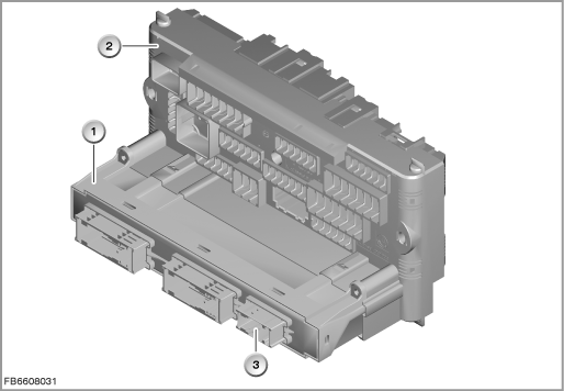
Index |
Explanation |
Index |
Explanation |
|---|---|---|---|
1 |
Junction box electronics (JBE) |
2 |
Front distribution box |
3 |
Plug connection for Park Distance Control, 18-pin |
|
|
System functions
PDC incorporates the following functions:
- Composite system
- Acoustic warnings
- Visual warning
- Check Control
- System limits
Composite system
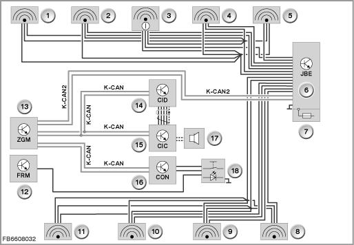
Index |
Explanation |
Index |
Explanation |
|---|---|---|---|
1 |
Ultrasonic sensor, front left side |
2 |
Front outer left ultrasonic sensor |
3 |
Front centre ultrasonic sensor |
4 |
Front outer right ultrasonic sensor |
5 |
Ultrasonic sensor, front right side |
6 |
Junction box electronics (JBE) |
7 |
Distribution box |
8 |
Rear outer right ultrasonic sensor |
9 |
Ultrasonic sensor, rear centre right |
10 |
Ultrasonic sensor, rear centre left |
11 |
Rear outer left ultrasonic sensor |
12 |
Footwell module (FRM) |
13 |
Central gateway module (ZGM) |
14 |
Central Information Display (CID) |
15 |
Car Information Computer (CIC) |
16 |
Controller (CON) |
17 |
Acoustic signal output |
18 |
Centre console operating unit |
Acoustic warnings
When an object is approached, the position is indicated accordingly by an intermittent tone. If e.g. an object is detected on the left behind the vehicle, the sound signal is issued from the rear left loudspeaker. The shorter the distance to an object, the shorter the intervals become. If the distance to a detected object is less than approx. 30 cm, a continuous tone sounds. If there are objects both in front of and behind the vehicle, an alternating continuous tone sounds.
An intermittent tone is interrupted after approx. 3 seconds under the following conditions:
- Coming to a halt in front of an object that is only detected by one of the corner sensors.
- Driving parallel to a wall.
The sound signal is switched off when transmission position P is engaged.
Visual warning
The visual PDC warnings are given in the Central Information Display (CID). The display appears as soon as the PDC is activated. The visual warnings are given earlier than the acoustic warnings. The effective range is approx. 2 metres at the front and rear. The graphic display is shown on the CID. The junction box electronics (JBE) deliver the distances between the ultrasonic sensor and registered object across the K-CAN. The PDC display on the CID is an overhead view of the vehicle with the effective range of the ultrasonic sensors.
The distance to objects detected is shown in the colours of traffic lights:
- Distance between 200 (250) and 101 centimetres: green
- Distance between 100 an 51 centimetres: yellow
- Distance less than 50 centimetres: red
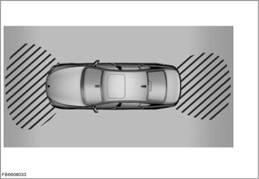
Check Control
If there is a fault in the PDC, a Check Control message is displayed.
On the PDC image, the areas in front of and behind the vehicle are shaded. PDC has failed. Check the system with diagnosis.
System limits
Important! Keep an eye on the traffic situation.
PDC is no substitute for your personal appraisal of the traffic situation. Check the traffic situation around the vehicle by looking around directly. Otherwise, road users or objects that are outside of the detection range of PDC, for example, could represent an accident risk. Loud noises outside and inside the vehicle can drown out the PDC signal tone.
During operation, system functions which require explanation can occur due to the limits of the functional range (for the driver): In the connection, read the Owner's Manual.
For information on the switch-on and switch-off conditions, also consult the Owner's Manual.
Notes for Service department
Procedure for troubleshooting
Note! Check mechanical condition of ultrasonic sensors.
Before troubleshooting, first check the mechanical condition of the ultrasonic sensors. Make sure that the ultrasonic sensors are located correctly in their brackets (decoupling element) and that they are free from dirt contamination, ice and snow.
Note! Avoid other interference variables during troubleshooting.
During troubleshooting, no object should be allowed to move closer than 40 centimetres within the effective range of the ultrasonic sensors.
Note! Check correct location of decoupling element on ultrasonic sensor.
The correct location of the correct decoupling element is important. Otherwise, transmission and reception will be impaired.
Note! Take care when mounting licence plate holders.
When mounting licence plates and licence plate holders, attention must be paid to ensuring that the middle sensor in the front bumper is not covered. Overlapping licence plate holders or deposits of dirt, snow and ice on the holders can diminish the function of the middle sensor.
Observe the following specifications for the licence plate holder:
- The licence plate must not protrude beyond the top edge of the licence plate holder.
- EURO: Use a drilling hole template to mount the licence plate. Comply with the regulations for mounting.
- China and USA: An additional licence plate support is mounted. This licence plate support, together with the licence plate, must not protrude beyond the top edge of the licence plate holder.
- The dealer licence plate holder (e.g. with dealer name) must not be mounted at the front.
Note! Do not perform any work on the ultrasonic sensor.
Ultrasonic sensors must not be painted. This means neither touching up nor complete painting.
Note! Cleaning the ultrasonic sensors.
With high-pressure cleaners, spray the ultrasonic sensors for a short period and from a distance of at least 10 centimetres.
No liability can be accepted for printing or other faults. Subject to changes of a technical nature