Roller mechanism
Roller mechanism
The electrically motorized reel system is an extension of the existing mechanical reel mechanism.
The electrically motorized reel system includes the following functions:
- Minimizing belt slack
(the seat belt lies as tightly as possible against the driver or passenger) - Stabilization of the seating position in a critical driving situation or in the event of a possible accident
(pretensioning of the seat belt to optimize the restraint system)
Brief description of components
The following components are described:
EMALI or EMARE: Control module for electrically motorized reel, left or right
The control module is connected to the drive for the electrically motorized reels and vehicle network by mean of 2 plug connections.
Following of evaluation of various signals and messages, the control module recognizes whether the belt has to be pretensioned.
The control module activates the drive for the electrically motorized reels directly.
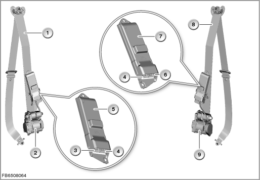
Index |
Explanation |
Index |
Explanation |
|---|---|---|---|
1 |
Front left seat belt |
2 |
Drive for left electrically motorized reel |
3 |
Plug connection to drive for electrically motorized reel on the left |
4 |
Plug-in connection to the vehicle network |
5 |
Control module for electrically motorized reel on the left (EMALI) |
6 |
Plug connection to drive for electrically motorized reel on the right |
7 |
Control module for electrically motorized reel on the right (EMARE) |
8 |
Front right seat belt |
9 |
Drive for right electrically motorized reel |
|
|
Drive for electrically motorized reels, left and right
The drive for the electrically motorized reel on the left and right consists essentially of the following parts:
- Electric motor
- Electronic module
- Transmission with clutch
(the clutch sets up the connection to the reel mechanism) - Reel mechanism
(mechanical function as before)
The electric motor is supplied with current (direction of motor rotation ”tension belt”) and moves a so-called output wheel in the clutch by means of a transmission. In the clutch, locking pawls move out and enter the clutch case. The clutch case is firmly connected to the drive shaft of the reel mechanism. This rolls up the seat belt.
To open the clutch, the direction of rotation of the electric motor must be briefly changed (opposite engine direction of rotation ”tension belt”).
If the connection between the electric motor and reel mechanism is interrupted, the reel mechanism works in the same way as a conventional mechanical reel mechanism.
There 2 Hall sensors integrated in the drive.
One Hall sensor picks up the direction of rotation and speed of the drive shaft for the reel mechanism.
The other Hall sensor picks up the rotary motion of the electric motor. The direction of rotation of the electric motor can be changed by means of the corresponding activation via the control module (EMALI control module or EMARE control module).
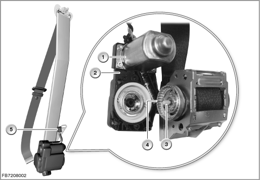
Index |
Explanation |
Index |
Explanation |
|---|---|---|---|
1 |
Electric motor |
2 |
Transmission with clutch |
3 |
Drive shaft for the reel mechanism |
4 |
Clutch case |
5 |
Plug connection to the control module for the electrically motorized reel on the left and/or right (EMALI or EMARE) |
|
|
System functions
When the seat belt is fastened (door closed), the control module for the electrically motorized reel on the left (EMALI control module) or the control module for the electrically motorized reel on the right (EMARE control module) activates the drive once over a certain period of time. With the help of the electric motor, the seatbelt strap is rolled up, thus removing the belt slack.
In critical driving situations or in the event of a possible accident, the control module also activates the drive. The duration is set in such a way that the drive is activated by the control module until a collision occurs or until a critical driving situation ends.
To calculate whether there is a critical driving situation (e.g. vehicle oversteering), the two control modules (EMALI control module and EMARE control module) use the data from the following systems:
- Integrated Chassis Management (ICM)
The ICM control module provides the systems in the entire vehicle with the dynamic driving state in the form of signals (e.g. data such as lateral and longitudinal acceleration, yaw rate). - Dynamic Stability Control (DSC)
The DSC control module delivers information such as the speed and brake pressure. - Crash safety module (ACSM stands for ”Advanced Crash Safety Module”)
The crash safety module sends a message with the status of the seat belt buckle contacts.
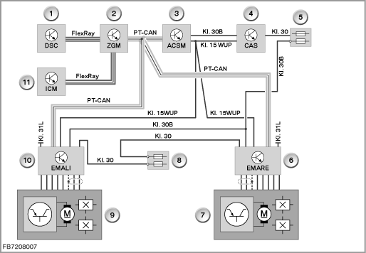
Index |
Explanation |
Index |
Explanation |
|---|---|---|---|
1 |
DSC (Dynamic Stability Control) |
2 |
Central gateway module (ZGM) |
3 |
Crash safety module (ACSM) |
4 |
Car Access System (CAS) |
5 |
Power distributor in junction box |
6 |
Control module for electrically motorized reel on the right (EMARE) |
7 |
Drive for right electrically motorized reel |
8 |
Rear distribution box |
9 |
Drive for left electrically motorized reel |
10 |
Control module for electrically motorized reel on the left (EMALI) |
11 |
Integrated Chassis Management (ICM) |
|
|
FlexRay |
Sub-bus |
Terminal 15 WUP |
Wake-up line (terminal 15 wake up) |
Terminal 30 |
Terminal 30 permanent positive |
Terminal 30B |
Terminal 30B, base operation |
Terminal 31L |
Terminal 31L, load earth |
PT-CAN |
Powertrain CAN |
Notes for Service department
General information
The drive for the electrically motorized reel can be activated via the BMW diagnosis system.
If the drive for the left electrically motorized reel fails, the following behaviour is to be expected:
- Fault memory entry in the control module for electrically motorized reel on the left (EMALI control module) or control module for electrically motorized reel on the right (EMARE control module)
- No effect on the mechanical function of the reel mechanism
No liability can be accepted for printing or other faults. Subject to changes of a technical nature