RDC antenna
RDC antenna
The RDC antenna is a component of the Tyre Pressure Monitor (RDC).
The tyre pressure monitor is a system for monitoring the tyre pressure while the vehicle is being driven. It is offered exclusively in the USA (legal requirement) and as an optional extra in Canada.
At the request of the RDC control module (cyclical, every 54 seconds), each wheel electronics system requests a message from the RDC transmitters (mounted in the wheel drop centre, low-frequency transmission path - 125 kHz). The message is then sent across a high-frequency transmission path (433 MHz) to the RDC antenna.
Among other things, this message contains the following information:
- Tyre pressure
- Tyre air temperature
- Battery status of the wheel electronics system
Functional description
The RDC antenna receives the high-frequency radio signals of the 4 wheel electronics systems. The measured values are sent either on request (cyclical, every 54 seconds) or automatically in the event of a breakdown (once per second) by the wheel electronics system.
At temperature values greater than 120 °C within the tyre, the wheel electronics system is switched off; on colling down to below 110 °C, it is switched on again.
The received radio signal are converted into a digital signal in the RDC antenna. This digital signal is forwarded on the bus to the RDC control module.
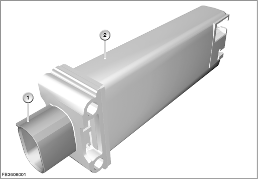
Index |
Explanation |
Index |
Explanation |
|---|---|---|---|
1 |
4-pin plug-in connection |
2 |
RDC antenna |
Structure and inner circuit
All 4 pins at each plug-in connection are used. The outside pins are earth connections. The inner pins are power supply and signal cable. The two earth connection are connected on a board in the electronic module. Only 3 cables are used in the wiring harness.
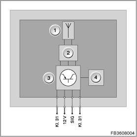
Index |
Explanation |
Index |
Explanation |
|---|---|---|---|
1 |
Reception antenna |
2 |
High-frequency receiver |
3 |
Electronic module |
4 |
Data interface |
Pin assignments
Pin |
Explanation |
|---|---|
Kl. 31 |
Terminal 31, earth connection |
12 V |
12 Volts, power supply |
SIG |
Signal line |
Kl. 31 |
Terminal 31, earth connection |
Target values
Observe the following target values for the RDC antenna:
Variable |
Value |
|---|---|
Voltage range |
6.5 to 18 V |
Maximum current consumption |
30 ± 5 mA |
Reception frequency (radio), version 1 |
315 ± 200 MHz |
Reception frequency (radio), version 2 |
433 ± 200 MHz |
Data transfer rate (radio) |
9.6 kBaud ± 10 % |
Temperature range |
-40 to 105 °C |
Diagnosis instructions
Failure of the component:
If the RDC antenna fails, the following behaviour is to be expected:
- Fault memory entry in the RDC control module
- Check Control message
- The RDC indicator and warning light lights up
No liability can be accepted for printing or other faults. Subject to changes of a technical nature