Left-hand operating unit on rear climate control
Left-hand operating unit on rear climate control
The left-hand operating unit on the rear climate control is used for individual operation of the rear climate control with left-right separation.
The operating unit regulates the air supply and air temperature (only cooling possible) in the rear via the left-hand roof air vent.
The left-hand operating unit on the rear climate control consists essentially of the following parts:
- Temperature dial
- Button for manual variation of the air flow rate
- 5 LEDs (for display of the selected air flow rate)
Functional description
The left-hand operating unit on the rear climate control is connected directly via a plug-in connection to the right-hand operating unit on the rear climate control. This means that all the settings for the left-hand operating unit on the rear climate control are picked up and digitized in the electronics of the right-hand operating unit on the rear climate control.
The right-hand operating unit on the rear climate control sends the signals on the LIN bus to the HKA control module.
The locating lights are controlled via terminal 58g by the footwell module.
After signal evaluation, the HKA control module activates the left mixed-air flap motor of the rear climate control, the left air-distribution-flap motor of the rear climate control, as well as the fan of the rear climate control by means of an output stage.
The LEDs are activated by the HKA control module via the LIN bus. The corresponding signal is sent to the LEDs in the left-hand operating unit on the rear climate control via the electronics in the right-hand operating unit on the rear climate control.
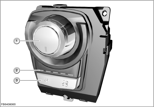
Index |
Explanation |
Index |
Explanation |
|---|---|---|---|
1 |
Temperature dial |
2 |
LEDs (for display of the selected air flow rate) |
3 |
Button for manual variation of the air flow rate |
|
|
Structure and inner circuit
The left-hand operating unit on the rear climate control is connected via an 18-pin plug-in connection to the vehicle network.
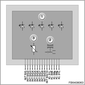
Index |
Explanation |
Index |
Explanation |
|---|---|---|---|
1 |
LEDs |
2 |
Button for manual variation of the air flow rate |
3 |
Temperature dial |
|
|
Pin assignments
Pin |
Explanation |
|---|---|
Terminal 31L |
Terminal 31, load earth (earth connection via right-hand operating unit on rear climate control) |
Terminal 30B |
Power supply for right-hand operating unit on rear climate control |
Terminal 58g |
Terminal 58g, locating lights (from footwell module via right-hand operating unit on the rear climate control) |
Terminal 58g |
Terminal 58g, locating lights (to left-hand roof air vent) |
Terminal 31 |
Terminal 31, earth connection for left-hand roof air vent |
INT_SIG |
Internal signal (between right-hand operating unit and left-hand operating unit) |
INT_SIG2 |
Internal signal (between right-hand operating unit and left-hand operating unit) |
INT_SIG3 |
Internal signal (between right-hand operating unit and left-hand operating unit) |
INT_SIG4 |
Internal signal (between right-hand operating unit and left-hand operating unit) |
INT_SIG5 |
Internal signal (between right-hand operating unit and left-hand operating unit) |
INT_SIG6 |
Internal signal (between right-hand operating unit and left-hand operating unit) |
INT_SIG7 |
Internal signal (between right-hand operating unit and left-hand operating unit) |
INT_SIG8 |
Internal signal (between right-hand operating unit and left-hand operating unit) |
INT_SIG9 |
Internal signal (between right-hand operating unit and left-hand operating unit) |
INT_SIG10 |
Internal signal (between right-hand operating unit and left-hand operating unit) |
3 pins not used. |
|
Target values
Observe the following target values for the left-hand operating unit on the rear climate control:
Variable |
Value |
|---|---|
Power supply |
12 V |
Voltage range |
8 to 16 V |
Temperature range |
-40 ± 85 °C |
Diagnosis instructions
Failure of the component:
If the left-hand operating unit in the rear climate control fails, the following behaviour is to be expected:
- Failure during operation:
- The current settings are retained.
If only the temperature dial or the button for manual variation of the air flow rate or both components fail, the current settings of the components concerned are retained.
If only the LED display fails, the HKA control module can no longer activate the LEDs to indicate the selected air flow rate. - No changes are displayed for the temperature dial and the button for manual variation of the air flow rate.
- Fault memory entry in the HKA control module
- The current settings are retained.
- Failure is determined on starting:
- The setting on the temperature dial is signalled internally as invalid. The mixed-air flap motor and the air-distribution-flap motor are no longer activated. This means the flap motors remain in their parking positions.
The parking position is a certain position to which a flap motor is move after the vehicle has been stopped and parked and after a specified waiting period (stored in the memory chip of the HKA control module). The flap motors are re-initialized to this parking position after starting up. - Fault memory entry in the HKA control module
- The setting on the temperature dial is signalled internally as invalid. The mixed-air flap motor and the air-distribution-flap motor are no longer activated. This means the flap motors remain in their parking positions.
No liability can be accepted for printing or other faults. Subject to changes of a technical nature