Combustion preheating control module
Combustion preheating control module
The combustion preheating control module is attached to the bracket of the high-pressure pump.
The glow system ensures reliable cold starting characteristics and smooth engine operation when the engine is cold. The DDE control module transmits the heating request to the combustion preheating control module. The combustion preheating control module puts the request into effect by activating the glow plugs by means of a pulse-width modulated signal. In addition, the combustion preheating control module reports diagnosis and state information across the LIN bus to the Digital Diesel Electronics.
Functional description
The required glow plug temperature is determined by the DDE control module on the basis of the following variables:
- Engine speed
- Intake air temperature
- Fuel injection rate
- Ambient pressure
- Vehicle voltage
- Status signal for starter enable
To activate glowing, the DDE sends the required glow plug temperature to the combustion preheating control module.
Across the LIN bus, the DDE also sends the following variables to the combustion preheating control module:
- Vehicle voltage
- Fuel injection rate per stroke
- Engine speed
The combustion preheating control module uses these 3 variables to determine the required current for the glow plugs.
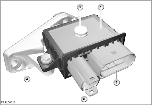
Index |
Explanation |
Index |
Explanation |
|---|---|---|---|
1 |
Combustion preheating control module |
2 |
12-pin plug-in connection |
3 |
1-pin plug-in connection |
4 |
High-pressure pump bracket |
5 |
Pressure compensation |
|
|
Glowing is activated in various operating states:
- Preheating
Preglowing is activated after switching on terminal 15. Pre-glowing is terminated under the following conditions:- Engine speed threshold of 42 rpm is exceeded (starter motor is activated by the DDE)
- Preglow time expired
The preglow time depends on the coolant temperature and is specified in a characteristic curve as follows: up the 3.5 seconds.
- Engine speed threshold of 42 rpm is exceeded (starter motor is activated by the DDE)
- Start preheating
When preglowing has been terminated by the preglow time elapsing, start standby glowing is activated. Start standby glowing is terminated under the following conditions:- 10 seconds of start standby glowing have elapsed
- Engine speed threshold of 42 rpm exceeded
- 10 seconds of start standby glowing have elapsed
- Start glowing
Start glowing is activated at every engine start if the coolant temperature is below 75 °C. Start glowing starts after the engine speed threshold of 42 rpm is exceeded. Start glowing is terminated under the following conditions:- The maximum start glow time of 60 seconds has elapsed
- Termination of the starting operation
- Coolant temperature of 75 °C is exceeded
- The maximum start glow time of 60 seconds has elapsed
- Emergency glowing
In the event of a failure in the communication between the DDE and combustion preheating control module for more than 1 second, emergency glowing is triggered for 3 minutes. Here, the combustion preheating control module uses safe values to prevent damage to the glow system. - Hidden glowing
Up to a coolant temperature of 30 °C, preglowing and start standby glowing are activated as so-called hidden glowing. Hidden glowing is triggered by the following signals:- Seat occupancy detection, driver side
- Seat belt buckle contact, driver
- Valid key
- Terminal R switched on
- Brake pressed
- Seat occupancy detection, driver side
- After-heating
At coolant temperatures below 30 °C, there is an after-heating period to improve idling and exhaust emission characteristics. - Partial-load glowing
After the engine start, partial-load glowing can take place below a coolant temperature of 75 °C. Activation of the glow plugs depends on the engine speed and load.
Structure and inner circuit
The glow system consists of the following components:
- DDE control module
- Electronic combustion preheating control module
- Ceramic glow plugs
- LIN bus as interface between the DDE control module and combustion preheating control module
The combustion preheating control module is supplied with terminal 30B by the junction box as well as terminal 30 by the starter motor.
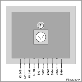
Index |
Explanation |
Index |
Explanation |
|---|---|---|---|
1 |
Combustion preheating control module |
|
|
Pin assignments
Pin |
Explanation |
|---|---|
Kl. 30B |
Terminal 30B, power supply for combustion preheating control module |
LIN |
LIN bus (Local Interconnect Network bus) |
Kl. 31E |
Electronic ground |
Kl. 30 |
Power supply for glow plug output stages |
SIG1 |
Activation of glow plug 1 |
SIG2 |
Activation of glow plug 2 |
SIG3 |
Activation of glow plug 3 |
SIG4 |
Activation of glow plug 4 |
SIG5 |
Activation of glow plug 5 |
SIG6 |
Activation of glow plug 6 |
Characteristic curve and target values
The ceramic glow plugs are designed for a voltage of 7.0 to 10.0 Volts. During glowing, on-board supply voltage can be applied briefly for rapid heating up. To maintain the glow plug temperature, the glow plugs are supplied with a PWM signal. This sets an effective voltage at the glow plugs that is lower than the on-board supply voltage.
Pre-glowing is controlled via a characteristic curve depending on the coolant temperature.
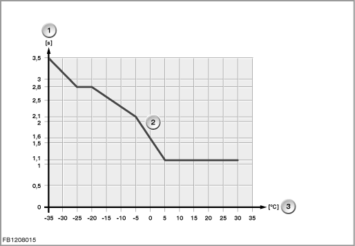
Index |
Explanation |
Index |
Explanation |
|---|---|---|---|
1 |
Time |
2 |
Characteristic curve for pre-glow |
3 |
Coolant temperature |
|
|
Observe the following target values for the glow system:
Variable |
Value |
|---|---|
Power supply of combustion preheating control module |
6 to 16 V |
Output current of glow plugs |
33 to 140 A |
Clock frequency for pulse width modulation |
30.1 to 30.9 Hz |
Temperature range (complete function) |
-40 to 85 °C |
Temperature range (restricted function) |
85 to 125 °C |
Diagnosis instructions
Failure of the component
If the combustion preheating control module fails, the following behaviour is to be expected:
- Fault memory entry in the engine control module
General information
The combustion preheating control module does not have its own fault memory. Faults in the glow system that are detected by the combustion preheating control module are reported to the Digital Diesel Electronics by the combustion preheating control module across the LIN bus. The faults are then stored in the DDE fault memory.
The ceramic glow plugs are sensitive to impacts and bending. Glow plugs that are dropped can be damaged.
No liability can be accepted for printing or other faults. Subject to changes of a technical nature