Damper satellite, rear left
Damper satellite, rear left
A damper satellite is fitted to each shock absorber.
The damper satellites are connected on the FlexRay.
The damper satellites are activated by the control module for vertical dynamics management (VDM).
Vertical dynamics management provides the following advantages:
- greater on-road comfort
- greater vehicle agility
- improved self-steering characteristics and load-change characteristics
Functional description
The damper satellites electronically control the damping forces. The damper satellites and the 2 EDC valves are inseparably connected to the shock absorbers. Each damper satellite contains its own vertical-acceleration sensor. What is new is that there is one EDC valve for the rebound stage and one for the discharge stage. This means that the control operation no longer has to be clocked so quickly.
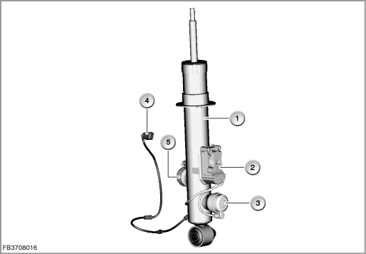
Index |
Explanation |
Index |
Explanation |
|---|---|---|---|
1 |
Shock absorber |
2 |
Damper satellite |
3 |
EDC valve discharge stage |
4 |
4-pin plug-in connection |
5 |
EDC valve rebound stage |
|
|
The damper satellites have the following tasks (among others):
- activating the EDC valves on the shock absorbers (characteristic map for damping)
- measuring the internal current (actual value) of the EDC valves and regulating to the target value.
- measuring the vertical acceleration of a wheel
The damper satellite also determines the wheel acceleration. The wheel acceleration is made available on the FlexRay for each individual wheel. The signal is used by the vertical dynamics management (VDM) for the control function.
Structure and inner circuit
The vertical dynamics management is composed of a central control module and 4 intelligent damper satellites that are fixed to the shock absorbers. The FlexRay data bus is the data line.
With a data transfer rate of 10 Mbit/s, FlexRay is significantly faster than the data buses employed on comparable vehicles (in the areas of body and powertrain/suspension).
The power is supplied by the VDM control module in pairs:
- Damper satellite front right and rear right
- Damper satellite front left and rear left
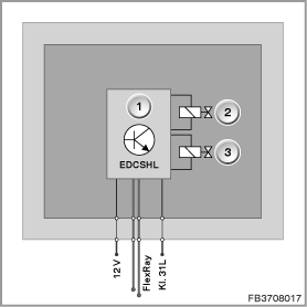
Index |
Explanation |
Index |
Explanation |
|---|---|---|---|
1 |
Damper satellite, rear left |
2 |
EDC valve rebound stage |
3 |
EDC valve discharge stage |
|
|
Note! Observe the connection of the FlexRay.
The FlexRay for the rear left damper satellites is connected to the control module for vertical dynamics management (VDM) via the central gateway module (ZGM).
Pin assignments
Pin |
Explanation |
|---|---|
12 V |
Power supply from VDM control module |
FlexRay |
2 bus connections, FlexRay |
Terminal 31L |
Terminal 31, load earth (to connector) |
Characteristic curve and target values
The electrically activated EDC valve on the shock absorber enables different damping force characteristic curves.
The vertical dynamics management uses the complete characteristic map of the rebound and discharge stages in for control in the ranges comfort to stability. In the event of a fault, the shock absorbers are set depending on the severity of the fault.
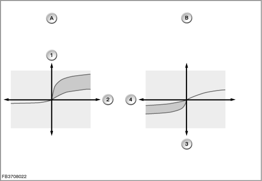
Index |
Explanation |
Index |
Explanation |
|---|---|---|---|
A |
Rebound stage |
B |
Discharge stage |
1 |
Damping force, rebound stage |
2 |
Piston speed, rebound stage |
3 |
Damping force, discharge stage |
4 |
Piston speed, discharge stage |
Observe the following target values for the damper satellites:
Variable |
Value |
|---|---|
Power supply |
9 to 16 Volts |
Temperature range |
-40 to 150 °C |
Diagnosis instructions
Failure of the component
If the damper satellite fails, the following behaviour is to be expected:
- Fault memory entry in the VDM control module
- Check Control message in the instrument cluster
Fail safe
The fail-safe is distinguished due to 3 levels:
- hard damping with severely restricted on-road comfort and the corresponding Check Control message
- medium damping with restricted on-road comfort and the corresponding Check Control message
- restricted control operation without effect and without a Check Control message
No liability can be accepted for printing or other faults. Subject to changes of a technical nature