Wheel-speed sensor, rear left and rear right
Wheel-speed sensor, rear left and rear right
An active wheel-speed sensor is fitted to each wheel.
The active wheel-speed sensors are connected to the DSC control module.
The entire signal processing takes place in the active wheel-speed sensors.
Functional description
The wheel speed is measured at a magnetic impulse wheel. The magnetic impulse wheel is divided into 96 increments per rotation of the wheel. Each increment change is detected by the active wheel-speed sensor and converted into a defined protocol of a pulse-width modulated signal.
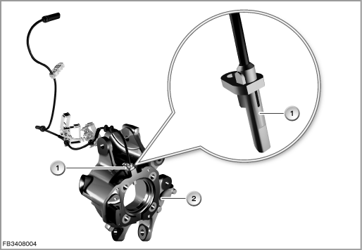
Index |
Explanation |
Index |
Explanation |
|---|---|---|---|
1 |
Wheel speed sensor |
2 |
Wheel carrier, rear left |
In contrast to earlier wheel-speed sensors, a current pulse is transmitted approximately every 0.75 seconds when the vehicle is stationary. The current impulse indicates the availability of the wheel-speed sensor.
Structure and inner circuit
The wheel bearing seal contains 48 pairs of magnetic poles. Here, the north and south poles alternate (comparable with the tooth and gap of an increment gear).
The wheel-speed sensor consists of 2 Hall sensors and an electronic evaluation unit.
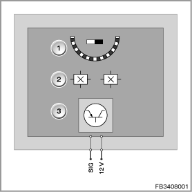
Index |
Explanation |
Index |
Explanation |
|---|---|---|---|
1 |
Increment wheel |
2 |
Hall sensors |
3 |
Electronic evaluation unit |
|
|
Pin assignments
Pin |
Explanation |
|---|---|
SIG |
Pulse-width modulated signal |
12 V |
Power supply from DSC control module |
Signal path and target values
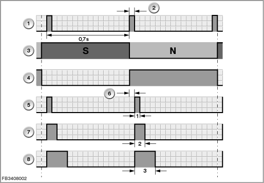
In addition to the wheel speed, other states are detected by the active wheel-speed sensor and transferred via the signal protocol:
- Direction of rotation of the wheel
- Air gap
- Vehicle at a standstill
If the wheel is at a standstill for longer than 1 second, a current impulse is sent approx. every 0.7 seconds.
The direction of rotation is sent to the DSC control module via a defined pulse width in the signal protocol.
The third additional item of information detected by the wheel-speed sensor is an upper air gap limit between the impulse wheel and sensor element. This information is also sent to the DSC control module for evaluation via the signal protocol.
Index |
Explanation |
Index |
Explanation |
|---|---|---|---|
1 |
Vehicle at a standstill |
2 |
Current impulse |
3 |
South pole (tooth), north pole (gap) |
4 |
Speed signal |
5 |
Air gap warning signal |
6 |
Start bit Low |
7 |
Direction of rotation left signal |
8 |
Direction of rotation right signal |
The DSC control module evaluates this information and can thus quickly and reliably detect the direction of travel, the vehicle at a standstill as well as possible air gap faults.
Observe the following target values for the wheel-speed sensor:
Variable |
Value |
|---|---|
Power supply |
5.0 to 20 Volts |
Signal frequency |
max. 5000 Hz |
Signal level |
Low: 7 mA High: 14 mA |
Pulse duty factor |
40 to 60 % |
Temperature range |
Sensor: |
Diagnosis instructions
Failure of the component
If the wheel-speed sensor fails, the following behaviour is to be expected:
- Fault memory entry in the DSC control module
- Check Control message
Clear fault memory
If the fault memory cannot be cleared after a repair, proceed in the following order:
- Remedy fault with ignition off
- Switch the ignition ON and then clear the fault memory
- Ignition Off
- Wait 5 to 10 seconds and then switch the ignition ON again
- Clear fault memory again
Note! The indicator and warning lamp in the instrument cluster remains lit up.
With certain faults, it is possible that the indicator and warning lights only go out after a short test drive.
No liability can be accepted for printing or other faults. Subject to changes of a technical nature