Brake pad wear sensor, front left
Brake pad wear sensor, front left
The front left brake pad wear sensor is attached to the left-hand brake caliper.
The condition of the brake pad is determined by the DSC control module. The calculation is supported at 2 positions by a signal from the brake pad wear sensors.
Functional description
The brake pad wear sensor is a sensor with a resistance measurement.
The brake pad wear sensors (front left and rear right on the internal brake pads) provide additional information on the thickness of the brake pad. The additional information (2 reference points) is used to synchronize the calculated value of the DSC with the real wear.
The reference points are at 6 mm and 4 mm.
The wear limit of the brake pad is at 3.7 mm.
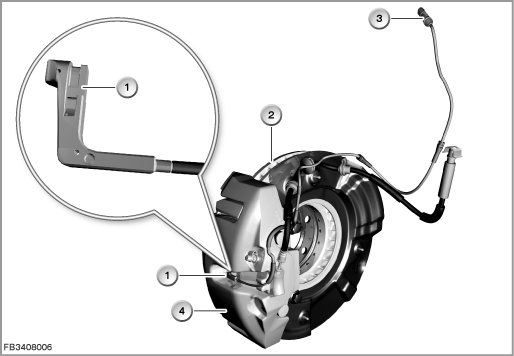
Index |
Explanation |
Index |
Explanation |
|---|---|---|---|
1 |
Brake pad wear sensor |
2 |
Brake disc |
3 |
2-pin plug-in connection |
4 |
Brake caliper |
A critical brake lining thickness is indicated in the instrument cluster by the Service Interval Display (Condition Based Service CBS) as well as the general brake warning light in red.
Structure and inner circuit
The brake pad wear sensor works in 2 stages. An additional resistor is integrated in the 2nd stage. The DSC uses the changed voltage measurement to calculate the current wear of the brake pad with the help of an algorithm.
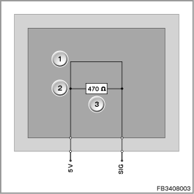
Index |
Explanation |
Index |
Explanation |
|---|---|---|---|
1 |
Reference point 6 mm |
2 |
Reference point 4 mm |
3 |
Resistance 470 |
|
|
Pin assignments
The brake pad wear sensor is supplied with 5 Volts by the DSC control module.
Pin |
Explanation |
|---|---|
5 V |
Power supply 5 Volt |
SIG |
Signal |
Measurement procedure and target values
The 2-stage sensor detects a break in wiring. The detection is active up to the 2nd stage at 4 mm. If the line breaks by then, the general brake warning lamp (yellow) is activated.
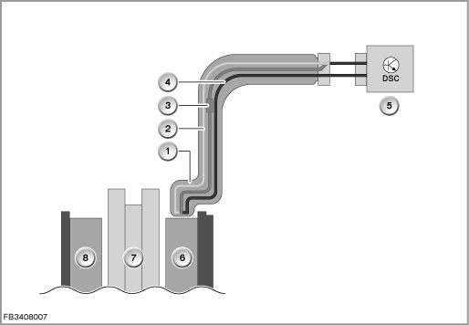
Index |
Explanation |
Index |
Explanation |
|---|---|---|---|
1 |
Brake pad wear sensor |
2 |
Conductor 1 |
3 |
Conductor 2 with resistor |
4 |
Conductor 3 |
5 |
DSC (Dynamic Stability Control) |
6 |
Brake pad, inside |
7 |
Brake disc |
8 |
Brake pad, outside |
Observe the following target values for the brake pad wear sensor:
Variable |
Value |
|---|---|
Voltage range |
0 to 5 V |
Resistance, stage 1 |
470 |
Resistance, stage 2 |
infinite |
Temperature range |
-40 to 150 °C |
Diagnosis instructions
Failure of the component
If the brake pad wear sensor fails, the following behaviour is to be expected:
- Fault memory entry in the Dynamic Stability Control
- As a substitute, calculation of the scope of service by the DSC for the Service Interval Display in the instrument cluster
- Activation of general brake warning lamp in the event of a break in wiring
Service functions
Important! Brake pad wear sensors must be intact.
It is only possible to reset the ”front brake pad” and ”rear brake pad” maintenance operations provided the brake pad wear sensor is not worn.
No liability can be accepted for printing or other faults. Subject to changes of a technical nature