Height-level sensor, rear left and rear right
Height-level sensor, rear left and rear right
The height-level sensors are installed on the rear axle (as series standard). The height-level sensor is bolted onto a bracket on the rear axle carrier.
Depending on the options fitted, there are 1-channel and 2-channel sensors on the rear axle. 2-channel sensors deliver the signal to the:
- Integrated Chassis Management (ICM)
- Control module for the electronic ride-height control (EHC = ride-height control)
The rear height-level sensors are electrically connected to the Integrated Chassis Management (ICM). The ICM places the signal on the FlexRay.
In the case of vehicles with ride-height control, the height-level sensor is also connected to the EHC control module (channel 2).
Functional description
The height-level sensor is a non-contact sensor.
The height-level sensor proportionally converts distances into an analogue voltage signal using an angle of rotation. The sensor can be rotated by 360°. The measuring range is 70° (depending on the installation location, See also 'Characteristic curve'). The signals are output as analogue electrical voltages.
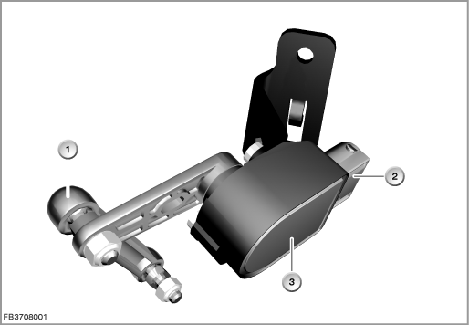
Index |
Explanation |
Index |
Explanation |
|---|---|---|---|
1 |
Coupling bar |
2 |
6-pin plug-in connection |
3 |
Height-level sensor |
|
|
The coupling bar converts the wheel lift into a rotary motion at the height-level sensor.
As the spring compresses and rebounds, the output voltage for the of the height-level sensor changes linearly. On compression, the output voltage rises. On rebound, the output voltage falls (rear right exactly vice versa, determined by the installation location)
Structure and inner circuit
The 2-channel height-level sensor consists of:
- Housing
- Ring magnet
- 2 Hall sensors
- 2 electronic evaluation units
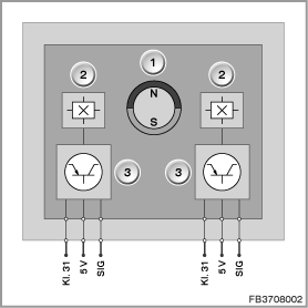
Index |
Explanation |
Index |
Explanation |
|---|---|---|---|
1 |
Ring magnet |
2 |
Hall-effect sensor |
3 |
Electronic evaluation unit |
|
|
Pin assignments
Pin |
Explanation |
|---|---|
Terminal 31 |
Earth connection channel 1 and 2 |
5 V |
5 Volts, power supply channel 1 and 2 |
SIG |
Signal 1 and 2 |
Characteristic curve and target values
The height-level sensor is supplied with 5 Volts by the ICM control module.
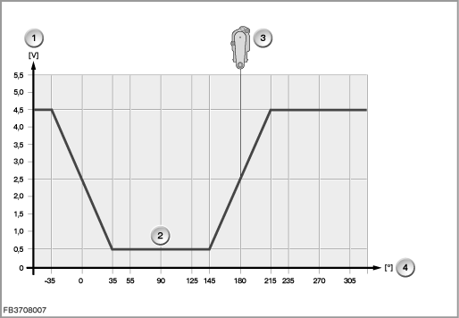
Index |
Explanation |
Index |
Explanation |
|---|---|---|---|
1 |
Signal voltage |
2 |
Characteristic curve of height-level sensor, rear left and right |
3 |
Installation location, rear left and right |
4 |
Angle of rotation in degrees |
Observe the following target values for the height-level sensor:
Variable |
Value |
|---|---|
Power supply |
4.5 to 5.5 V |
Output voltage at the sensor output in the event of failure of the power supply |
max. 2% |
Output voltage at the sensor output in the event of interruption of the earth lead |
min. 98% |
Overvoltage |
max. 18 V |
Short circuit protection (all pins) |
max. 16 V |
Maximum constant current consumption per channel (at U = 5.5 Volt) |
16 mA |
ON current (at U = 5.5 Volt) |
20 mA |
Diagnosis instructions
Failure of the component
If the height-level sensor fails, the following behaviour is to be expected:
- Fault memory entry in the ICM
- No control operation of the vertical dynamics management
- No headlamp range control
- No control operation of the ride-height control
General information
Note! Analogue sensors cannot be evaluated by several control modules.
The sensor issues an analogue voltage signal. This signal is measured in the control module against a resistor. If a number of control modules were to receive the voltage signal, this would result in parallel switching of the resistors and thus a falsification of the measured value. This is why a 2-channel sensor must be Xenon lights on the rear axle of vehicles with ride-height control and xenon light as well as adaptive headlight or Head Up display or vertical dynamics management.
Service functions
Important! Run a calibration of the height-level sensors.
After replacement of the control module (EHC, ICM) as well as of a height-level sensor, the calibration values of the height-level sensors must be relearned. The service function ”ride-height calibration” on the BMW diagnosis system must be used.
No liability can be accepted for printing or other faults. Subject to changes of a technical nature