Intelligent battery sensor
Intelligent battery sensor
The intelligent sensor is attached to the negative battery terminal.
The intelligent battery sensor is now connected to the engine control module across a LIN bus.
It used to be the case that the battery sensors were connected to the engine management system via the bit-serial data interface (BSD).
The intelligent battery sensor is an extremely important component for energy management in the overall vehicle.
Functional description
The intelligent battery sensor (IBS) is a mechatronic component for monitoring the battery status. The following measurement variables are registered:
- Terminal voltage
- Charge current and discharge current
- Temperature of the battery terminal
The designation ”intelligent” in the context of the battery sensor refers to an integrated microprocessor with software. Special time-critical measured variables are processed upstream in a processor. The results are then forwarded (with low data rate) to the engine control module.
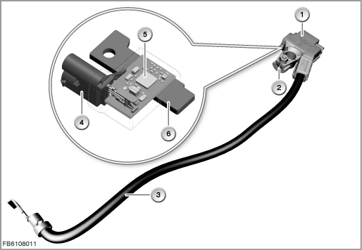
Index |
Explanation |
Index |
Explanation |
|---|---|---|---|
1 |
Intelligent battery sensor |
2 |
Battery negative terminal |
3 |
Ground cable |
4 |
Plug-in connection |
5 |
Circuit board with microprocessor and temperature sensor |
6 |
Measuring resistor (= shunt) |
The intelligent battery sensor sends the data across the LIN bus to the engine management system. The software in the engine management system controls communication with the intelligent battery sensor. Calculation of the battery condition (SOH = State of Health) as well as calculation of the battery charge state (SOC = State of Charge) are carried out in the engine management system.
The individual functions of the intelligent battery sensor are:
- Continuous measurement of battery data in every operating condition of the vehicle
- Balancing the charge current as well as discharge current of the battery
- Monitoring the battery charge state and activating of the electrical energy management and power management. Countermeasures in the case of a critical battery charge state (limit of starting capability of the battery).
- Determining initial data for calibration of the battery charge state
- Calculation of the course of the starting current to determine the battery condition
- Closed-circuit current monitoring
- Data transfer to the engine control module (DME or DDE)
- Self-diagnosis
- Fully automatic updates of the algorithm parameters and parameters for self-diagnosis via the engine management system
- Capability to wake itself in critical states (battery charging low and/or closed-circuit current increased) during the Sleep mode and to output a corresponding message to the junction box electronics (JBE). Depending on the type of message and the vehicle state, the JBE carries out various actions, e.g. shutdown of terminal 30F
In the time between engine OFF and shutdown of the DME main relay, the intelligent battery sensor receives the following information from the engine management system:
Maximum charge volume that can be drawn for a reliable engine start.
After shutdown of the DME main relay, the intelligent battery sensor continuously checks the battery charge state and closed-circuit current consumption.
Structure and inner circuit
The intelligent battery sensor is structured as follows:
- Circuit board with electronic evaluation unit and temperature sensor
- Microprocessor with software
- Resistor for current measurement (shunt: low-impedance electrical resistor used to measure currents)
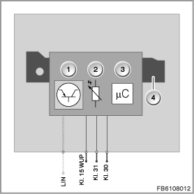
Index |
Explanation |
Index |
Explanation |
|---|---|---|---|
1 |
Board |
2 |
Temperature sensor |
3 |
Microprocessor with software |
4 |
Measuring resistor |
Pin assignments
Pin |
Explanation |
|---|---|
LIN |
LIN bus (Local Interconnect Network bus) |
Kl. 15 WUP |
Terminal 15 wake-up |
Terminal 30 |
12 Volts, power supply |
Terminal 31 |
Ground connection |
Measurement procedure and target values
For data transmission, the intelligent battery sensor is connected to the DME (Digital Motor Electronics) or DDE (Digital Diesel Electronics) via the LIN bus.
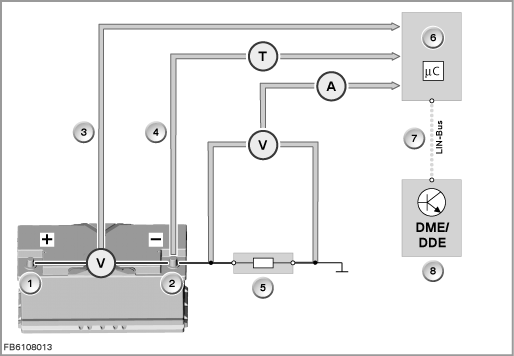
Index |
Explanation |
Index |
Explanation |
|---|---|---|---|
1 |
Positive battery terminal |
2 |
Negative battery terminal |
3 |
Measurement of the battery voltage between the positive battery terminal and negative battery terminal |
4 |
Measurement of the battery temperature (T) |
5 |
Current measurement (A) indirect, via the proportional voltage drop (V) at the measuring resistor |
6 |
Microprocessor in the intelligent battery sensor |
7 |
LIN bus |
8 |
Engine management system (DME or DDE) |
The measurement data is queried while the vehicle is being driven and when the vehicle is at a standstill:
- Vehicle being driven:
- Calculation of the battery status as basis for the battery charge state (SOC: ”State of Charge”) and battery condition (SOH: ”State of Health”). Balancing the charge and discharge current of the battery.
- Calculation of the current characteristics on engine start to ascertain the battery condition.
- Calculation of the battery status as basis for the battery charge state (SOC: ”State of Charge”) and battery condition (SOH: ”State of Health”). Balancing the charge and discharge current of the battery.
- When stationary:
When the vehicle is at a standstill, the measured values are queried in cycles to detect energy losses.
The intelligent battery sensor is programmed in such a way that it wakes up every 14 seconds so that it can update the measured values by means of a new measurement. The measurement takes approx. 50 milliseconds. The measured values are entered in the battery sensor in the memory for recording the closed-circuit current.
After restarting the engine, the engine management system reads out the course of the closed-circuit current. If there is a deviation from the defined course of the closed-circuit current, an entry is made in the fault memory in the engine control module.
Observe the following target values for the intelligent battery sensor:
Variable |
Value |
|---|---|
Closed-circuit current |
-2.5 to 10 Amperes |
Operating current |
-200 to 200 Amperes |
Starting current |
0 to 1000 Amperes |
Voltage range |
6 to 16.5 Volts |
Temperature range |
-20 to 105 °C |
Diagnosis instructions
Failure of the component
If the intelligent battery sensor fails, the following behaviour is to be expected:
- Fault memory entry in the DME or DDE
- Power management in emergency operating mode (e.g. reduction of consumer units)
- No function for automatic engine start-stop function
General information
Note! No commissioning is necessary.
Directly after assembly on the battery terminal, bolting onto the ground support point and connection of the signal line, the intelligent battery sensor is fully functional. The base variables of current, voltage and temperature can be called up immediately.
Diagnosis instructions
Waking of the vehicle (via JBE) due to increased closed-circuit current can occur up to 3 times.
Depending on the vehicle state and reason for waking, one of the following actions is executed by the JBE:
- Waking of the vehicle so that the engine management system can send shutdown requests to auxiliary consumer units.
- Resetting terminal 30F (whereby the vehicle does not wakeup)
- Shutdown of terminal 30F (whereby the vehicle does not wakeup)
- No action (only fault memory entry)
In all cases, a fault memory entry is generated.
No liability can be accepted for printing or other faults. Subject to changes of a technical nature