AUC sensor
AUC sensor
The sensor for automatic recirculated air control (AUC sensor) is fitted on the micro-filter compartment.
The AUC sensor evaluates the concentration of carbon monoxide and nitrogen oxides in the intake fresh air.
If the AUC sensor measures an excessive emission value, the control module of the automatic climate control (IHKA control module) switches to the recirculated-air mode (precondition: IHKA in the automatic mode).
Because of the lack of a fresh-air supply, the air-recirculation mode is only available for a limited period of time.
When the engine is started and the AUC function activated, fresh air is always selected for approx. 40 seconds due to the warming phase of the AUC sensor.
Functional description
The sensor is supplied with voltage as of terminal 15N on. The sensor element requires an operating temperature of approx. 300 °C.
The electronics in the AUC sensor control the clocking of the heater voltage (depending on the target and actual temperature).
The AUC sensor reaches operational status after 30 seconds and reacts to changes in the ambient air.
The AUC sensor converts the detected air quality (also referred as air grade) into an electrical signal. To simplify processing of the information, the air quality in 10 levels:
- Level 0 to Level 10 (clean to severely contaminated)
The AUC sensor sends the corresponding level as a digital signal on the LIN bus to the junction box electronics (JBE).
The junction box electronics send the digital signal on the CAN bus to the IHKA control module.
According to the internal measuring interval, the information is updated every second.
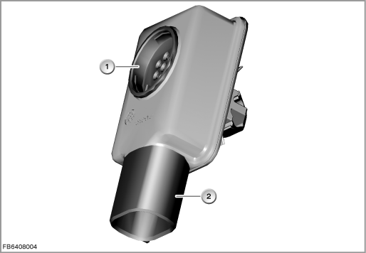
Index |
Explanation |
Index |
Explanation |
|---|---|---|---|
1 |
Sensor for automatic recirculated air control (AUC sensor) |
2 |
3-pin plug-in connection |
Structure and inner circuit
The AUC sensor is a metal oxide sensor. This sensor is highly sensitive to various smells and pollutants that are typical of traffic.
The AUC sensor consists of 2 resistor elements and an electronic module.
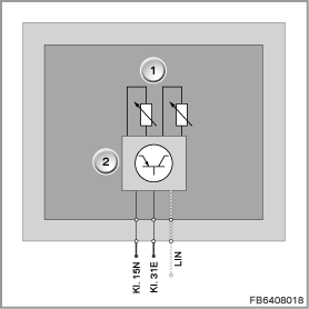
Index |
Explanation |
Index |
Explanation |
|---|---|---|---|
1 |
Resistance elements |
2 |
Electronic module |
Pin assignments
Pin |
Explanation |
|---|---|
Kl. 15N |
Terminal 15 after-run, power supply |
Kl. 31E |
Terminal 31, electronics earth |
LIN |
LIN bus |
Target values
Observe the following target values for the AUC sensor:
Variable |
Value |
|---|---|
Voltage range |
9 to 16.5 V |
Overvoltage |
Greater than 18.5 V |
Undervoltage |
Less than 8.5 V |
Maximum power consumption |
Less than 1 W |
Response time |
Less than 1 s |
Temperature range |
-40 to 85 °C |
Diagnosis instructions
Failure of the component:
If the component fails, the following behaviour is to be expected:
- Fault memory entry in the junction box electronics (JBE)
- Substitute value from the IHKA control module: Air quality, stage 0
(stage 0 corresponds to clean air) - Automatic recirculated air control not possible
No liability can be accepted for printing or other faults. Subject to changes of a technical nature