Ventilation temperature sensor, front left
Ventilation temperature sensor, front left
The front left ventilation temperature sensor is a component of the integrated heating / air-conditioning system (IHKA) with left-right separation.
The sensor measures the delivery temperature directly at the centre ventilating flap on the driver's side.
A total of 2 ventilation temperature sensors are installed (at the ventilation flap on the driver's side and at the ventilation flap on the passenger's side). The 2 ventilation temperature sensors are identical components.
The IHKA control module evaluates the signal from the front left ventilation temperature sensor. The IHKA control module uses this message to regulate the centre left ventilation-flap motor.
Functional description
The ventilation temperature sensor is a hot conductor or NTC resistor (”NTC” stands for ”Negative Temperature Coefficient”).
The hot conductor means that the variable ”temperature” can be converted into the variable ”resistance” which can be electrically evaluated. The current-conducting materials in the hot conductor conduct current better at high temperatures than at low temperatures. That means: With rising temperatures, the resistance falls.
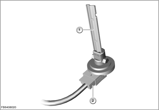
Index |
Explanation |
Index |
Explanation |
|---|---|---|---|
1 |
Ventilation temperature sensor |
2 |
2-pin plug-in connection |
Structure and inner circuit
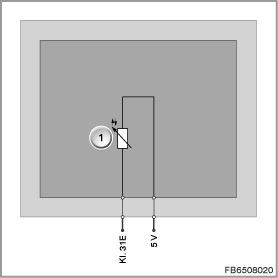
The ventilation temperature sensor is supplied with 5 Volts by the IHKA control module. In order to balance out internal temperature effects, the hot conductor is operated with low current. This means that the outer ambient temperature is decisive for the resistance value.
Index |
Explanation |
Index |
Explanation |
|---|---|---|---|
1 |
Hot conductor |
|
|
Pin assignments
Pin |
Explanation |
|---|---|
5 V |
5 Volts, power supply |
Kl. 31E |
Terminal 31, electronics earth |
Characteristic curve and target values
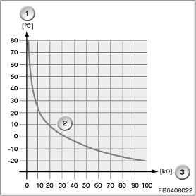
Each temperature change at the hot conductor leads to a change in the voltage signal. The evaluation takes place in the IHKA control module.
Index |
Explanation |
Index |
Explanation |
|---|---|---|---|
1 |
Temperature in degrees Celsius (°C) |
2 |
Characteristic curve for hot conductor |
3 |
Resistance in Kiloohms (k) |
|
|
Observe the following target values for the ventilation temperature sensor:
Variable |
Value |
|---|---|
Power supply |
5 V |
Temperature range |
-40 to 85 °C |
Resistance range (measuring range) |
1.2 to 100 k |
Diagnosis instructions
Failure of the component:
If the front left ventilation temperature sensor fails, the following behaviour is to be expected:
- Fault memory entry in the IHKA control module
- Substitute value from the IHKA control module: 20 °C
No liability can be accepted for printing or other faults. Subject to changes of a technical nature