Oil-level switch
Oil-level switch
The oil reservoir contains an oil filter and an oil-level switch with float. In contrast to the oil-level switch, the oil filter cannot be replaced separately. A dipstick that enables a check of the oil level is attached to the screw cap.
Functional description
The oil-level switch detects whether the required oil level in the oil reservoir is exceeded or undershot. The VDM control module sends the signal on the bus system to the instrument cluster. The instrument cluster issues a Check Control message. Normal motion of the oil in the oil reservoir does not lead to a Check Control message.
There is a permanent magnet in the moving float; this triggers the reed contact in the oil-level switch firmly fitted in the reservoir. Here, the reed contact converts the float movement into an electrical signal. If the oil level is above the minimum level, the reed contact is closed (approx. 10 mm below the MIN mark).
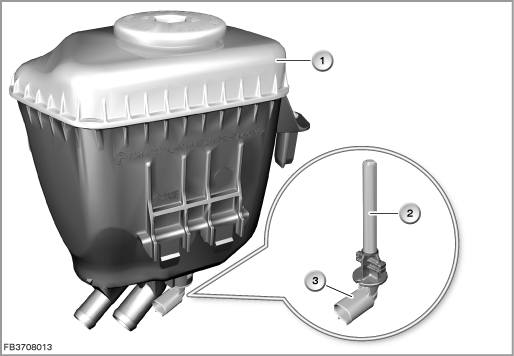
Index |
Explanation |
Index |
Explanation |
|---|---|---|---|
1 |
Oil tank |
2 |
Oil-level switch |
3 |
2-pin plug-in connection |
|
|
On the oil-level switch, short circuit or break in wiring cannot be detected. A break in wiring is interpreted as oil loss. A short circuit is not detected.
Structure and inner circuit
The reed contact has the effect of a switch. If the reed contact is activated, ground is switched through to the VDM control module.
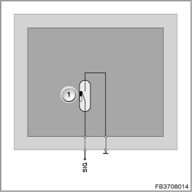
Index |
Explanation |
Index |
Explanation |
|---|---|---|---|
1 |
Reed contact in the oil-level switch |
|
|
Pin assignments
Pin |
Explanation |
|---|---|
SIG |
Reed contact signal |
Characteristic curve for filter element as well as bypass valve and target values
The oil reservoir contains a mechanical bypass valve that opens if the filter element is soiled. The bypass valve opens at approx. 3 bar overpressure.
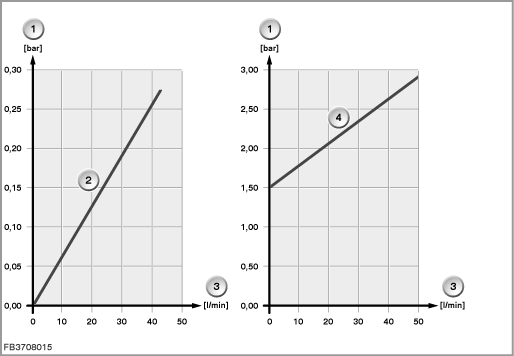
Index |
Explanation |
Index |
Explanation |
|---|---|---|---|
1 |
Differential pressure |
2 |
Characteristic curve for flow through filter element |
3 |
Volumetric flow |
4 |
Characteristic curve for flow through bypass valve |
Observe the following target values for the oil-level switch:
Variable |
Value |
|---|---|
Maximum current consumption |
15 mA |
Maximum contact resistance |
500 m |
Temperature range |
-40 °C to 120 °C |
Diagnosis instructions
Failure of the component
If the oil-level switch fails, the following behaviour is to be expected:
- Fault memory entry in the VDM
- Output of a Check Control message in the instrument cluster
- Fail-safe, steering power assistance also affected
General information
On checking the oil level, the influence of the oil temperature must be taken into account (volume expansion). There is a ”MAX” mark on the oil dipstick. The mark indicates the maximum permitted oil level measured at room temperature (20 °C). Due to heat expansion, at oil temperatures of 50 to 70 °C the oil level is approx. 15 mm above the mark. With regard to the oil level, follow the repair instructions.
Vehicles without active roll stabilization can be recognized by the lack of oil-level switch.
No liability can be accepted for printing or other faults. Subject to changes of a technical nature