Charge-air-temperature sensor
Charge-air-temperature sensor
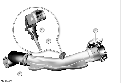
The charge-air temperature sensor is located on the charge-air pipe between the charge-air cooler and the throttle valve.
The charge-air temperature sensor detects the temperature of the intake air compressed by the turbocharger and cooled by the charge-air cooler.
Functional description
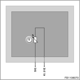
A temperature-dependent electrical resistor is used for temperature detection. The circuit contains a power diplexer where the resistance can be measured depending on the temperature. This is converted into a temperature using a characteristic curve that is specific to the sensor.
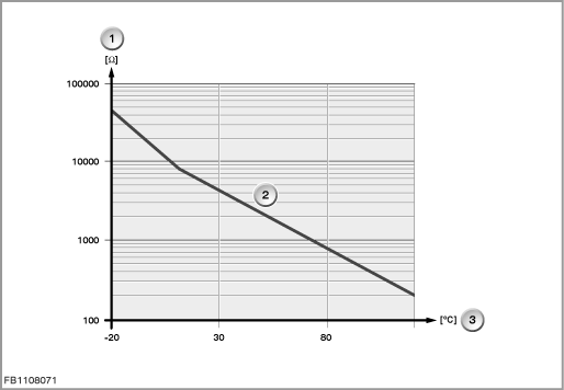
A hot conductor (NTC) is installed in the charge-air temperature sensor; the resistance value of this hot conductor falls with rising temperature. The resistance changes depending on the temperature from 76 k to 88 , which corresponds to a temperature of -40 °C to 120 °C.
Index |
Explanation |
Index |
Explanation |
|---|---|---|---|
1 |
Intake air temperature-intake manifold pressure sensor |
2 |
Throttle-valve actuator |
3 |
Intake air collector |
4 |
2-pin plug-in connection |
Structure and inner circuit
The intake-air temperature / intake-manifold pressure sensor is connected by means of a 2-pin plug-in connection.
The sensor is supplied with ground by the engine management system.
Index |
Explanation |
Index |
Explanation |
|---|---|---|---|
1 |
Charge-air-temperature sensor |
|
|
Pin assignments
Pin |
Explanation |
|---|---|
SIG |
Charge-air temperature signal |
Kl. 31E |
Terminal 31, electronics earth |
Characteristic curve and target values
The charge-air temperature information is sent to the engine management system across a signal line. The charge-air temperature is used for substitute calculation of the air mass. This ensures plausibility of the value of the hot-film air-mass sensor. If the hot-film air-mass sensor fails, the substitute value is used to determine the fuel quantity measurement and exhaust gas recirculation rate.
Index |
Explanation |
Index |
Explanation |
|---|---|---|---|
1 |
Resistance |
2 |
Characteristic curve for hot conductor (NTC) |
3 |
Temperature |
4 |
|
Observe the following target values for the charge-air temperature sensor:
Variable |
Value |
|---|---|
Voltage range for charge-air temperature sensor |
0.3 to 3.3 Volts |
Response time |
Less than 25 s |
Resolution of intake-air temperature |
± 1 °C |
Maximum output current |
10 mA |
Temperature range |
-40 °C to 120 °C |
Diagnosis instructions
Failure of the component
If the charge-air temperature sensor fails, the following behaviour is to be expected:
- Fault memory entry in the engine control module
- Deactivation of charge-air pressure control
- Exhaust gas recirculation is deactivated
- Limitation to fuel injection rate (torque limitation)
No liability can be accepted for printing or other faults. Subject to changes of a technical nature