Ultrasonic sensor
Ultrasonic sensor
Park Distance Control (i.e.: parking aid) assists the driver when he is parking and manoeuvring in tight spaces. This means that even small parking spaces can be used. At the same time, the amount of parking damage is reduced. The PDC runs a distance measurement in relation to objects in the pickup range by means of ultrasonic sensors.
New: The PDC is integrated in the junction box electronics (JBE).
There are now 5 ultrasonic sensors installed in the front bumper (F01/F02).
Reason: Optimized geometry for monitoring.
There 4 ultrasonic sensors installed in the rear bumper.
The ultrasonic sensors in the front and rear bumpers are electrically and geometrically identical.
Functional description
The ultrasonic sensors emit ultrasonic pulses. These ultrasonic impulses are reflected by obstacles (echo impulse).
The ultrasonic sensors pick up and amplify these echo impulses. The amplified echo pulses are then converted into a digital signal.
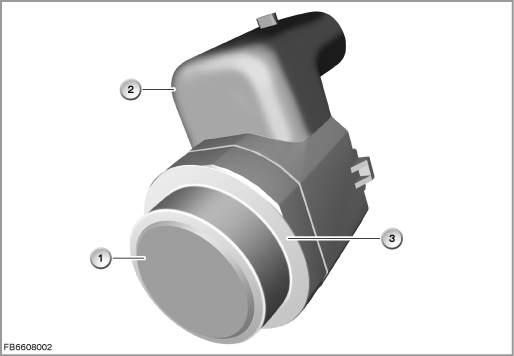
Index |
Explanation |
Index |
Explanation |
|---|---|---|---|
1 |
Ultrasonic sensor |
2 |
3-pin plug-in connection |
3 |
Decoupling element |
|
|
Each ultrasonic sensor has its own electronics as well as its own data line to the PDC control module.
When the ignition is ON, the PDC control module supplies the ultrasonic sensor (working memory) with current vehicle data. The ultrasonic sensors are activated by the PDC control module, either in combined transmit and receive mode or in pure receive mode.
Combined transmit and receive mode
In the combined transmit and receive mode, the ultrasonic sensors of a bumper first transmit in succession a package of ultrasonic impulses. Subsequently, the ultrasonic sensors pick up the echo impulse that is reflected by an object in the pickup range. This echo impulse is amplified in the ultrasonic sensor and forwarded as a digital signal to the PDC control module. The PDC control module uses the runtime of the echo impulse to calculate the distance to the object.
Receive mode
In the receive mode, an ultrasonic sensor picks up the echo impulses sent by neighbouring ultrasonic sensors. The PDC control module can this evaluate the signals from up to 3 ultrasonic sensors (”trilateration” = the neighbouring sensors also ”listen”). This signal evaluation of a number of ultrasonic sensors is used to calculate the minimum distance between the vehicle and the object.
Structure and inner circuit
The ultrasonic sensors in the front and rear bumpers are electrically and geometrically identical. The ultrasonic sensors have a smaller diaphragm (advantageous for the design). The membrane is always painted. The membrane can be designed as smaller due to the decoupling element on the sensor housing.
The ultrasonic sensor has an encodable/programmable working memory in its electronic circuitry. This means that the sensitivity of the echo reception can be specifically influenced. The ultrasonic sensors can thus be used in all models.
All the ultrasonic sensors have their own electronics. The front and rear ultrasonic sensors have a joint power supply and earth contact.
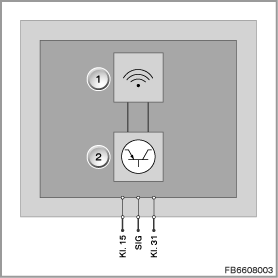
Index |
Explanation |
Index |
Explanation |
|---|---|---|---|
1 |
Transceiver unit (piezoceramic) |
2 |
Electronic module with electronic evaluation unit |
Pin assignments
Pin |
Explanation |
|---|---|
Kl. 15 |
Terminal 15, power supply |
SIG |
Signal |
Terminal 31 |
Ground connection |
Measurement procedure and target values
The ultrasonic sensors are supplied with terminal 15 by the PDC control module.
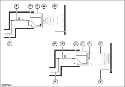
Index |
Explanation |
Index |
Explanation |
|---|---|---|---|
1 |
Electronic module, including main memory |
2 |
Piezo-ceramic element |
3 |
Decoupling element |
4 |
Diaphragm |
5 |
Ultrasonic wave |
6 |
Obstacle |
7 |
Plug-in connection |
|
|
Observe the following target values for the ultrasonic sensor:
Variable |
Value |
|---|---|
Power supply |
9 to 16 Volts |
Ultrasonic frequency |
50 kHz |
Range |
250 cm |
Settling time of membrane |
approx. 1 ms |
Temperature range |
-40 to 85 °C |
Diagnosis instructions
Failure of the component
If the ultrasonic sensor fails, the following behaviour is to be expected:
- Fault memory entry in the junction box electronics (JBE)
- Check Control message and grey PDC image
General information
Important! The PDC is integrated in the junction box electronics.
The PDC behaves like a control module in the control module. Physically, the PDC is in the JBE. However, the PDC has its own control module address.
Note! Check mechanical condition of ultrasonic sensors.
Before troubleshooting, first check the mechanical condition of the ultrasonic sensors. Make sure that the ultrasonic sensors are located correctly in their brackets (decoupling element) and that they are free from dirt contamination, ice and snow.
Note! Do not perform any work on the ultrasonic sensor.
Ultrasonic sensors must not be painted. This means neither touching up nor complete painting.
Note! Cleaning the ultrasonic sensors.
With high-pressure cleaners, spray the ultrasonic sensors for a short period and from a distance of at least 10 centimetres.
No liability can be accepted for printing or other faults. Subject to changes of a technical nature