Rail-pressure regulating valve
Rail-pressure regulating valve
The rail-pressure regulating valve is bolted onto the end of the fuel-distribution pipe (rail).
The high pressure pump constantly generates the system pressure in the rail. Two valves are used to control the required rail pressure:
- Rail-pressure regulating valve
- Flow regulating valve (see corresponding functional description)
Functional description
With active pressure regulation, the DDE activates the rail-pressure regulating valve with various pulse duty factors. In doing so, the DDE regulates the rail pressure to the calculated target pressure. The fuel that is taken off is fed by the rail-pressure regulating valve into the return line. Depending on the type of activation, the pressure control valve allows more or less fuel to flow from the high pressure side into the virtually depressurized return line. The more fuel flows into the return flow the lower the pressure build-up on the high-pressure side.
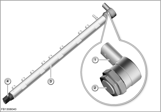
Index |
Explanation |
Index |
Explanation |
|---|---|---|---|
1 |
2-pin plug-in connection |
2 |
Rail-pressure regulating valve |
3 |
Fuel-distribution pipe (rail) |
4 |
Rail pressure sensor |
Structure and inner circuit
The rail-pressure sensor is connected by means of a 2-pin plug-in connection.
The rail-pressure regulating valve is supplied with voltage via terminal 15N.
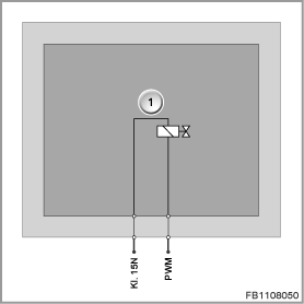
Index |
Explanation |
Index |
Explanation |
|---|---|---|---|
1 |
Rail-pressure regulating valve |
|
|
Pin assignments
Pin |
Explanation |
|---|---|
Kl. 15N |
Terminal 15, power supply |
PWM |
Pulse-width modulated activation of the rail-pressure regulating valve |
Sectional view and target values
When the rail-pressure regulating valve is not supplied with current, the rail-pressure regulating valve is opened. This reduces the rail pressure to zero.
Activation of the rail-pressure regulating valve supplies the coil with current. This energizes the armature plate and the pressure pin presses the valve ball into the valve seat. The stronger the valve ball is pressed into the valve seat, the less fuel can flow into the return flow.
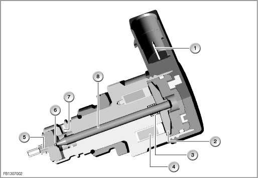
Index |
Explanation |
Index |
Explanation |
|---|---|---|---|
1 |
2-pin plug-in connection |
2 |
Armature plate |
3 |
Opening spring |
4 |
Coil for electromagnet |
5 |
Bore hole towards the high-pressure side |
6 |
Ball valve |
7 |
Bore hole to return line |
8 |
Pressure pin |
Observe the following target values for the rail-pressure regulating valve:
Variable |
Value |
|---|---|
Power supply |
12 Volts |
Pulse duty factor |
30 to 95 % |
Coil resistance at 20 °C |
3.42 to 3.78 |
Maximum output current |
1.7 A |
Temperature range |
-40 °C to 130 °C |
Diagnosis instructions
Failure of the component
If the rail-pressure regulating valve fails, the following behaviour is to be expected:
- Fault memory entry in the engine control module
- If activation of the rail-pressure regulating valve is interrupted or there is a short circuit to ground, the engine shuts down.
General information
The service function 'Rail-pressure regulating valve adaptation' must be run if the rail-pressure regulating valve is replaced. Execution of the service function deletes the adaptation value. After installation of the new rail-pressure regulating valve, the new value is learned with the engine running and stored in the DDE.
No liability can be accepted for printing or other faults. Subject to changes of a technical nature