Charge-air pressure controller
Charge-air pressure controller
The charge-air pressure control ensures setting of the right charge-air pressure at any point in time. Depending on the operating point, the charge-air pressure is controlled or regulated. In controlled operation, the charge-air pressure controller is activated depending on the operating point with pulse duty factors predefined in characteristic maps.
In regulated operation, the actual charge-air pressure is picked up via the charge-air pressure sensor. The DDE control module uses this to calculate the required pulse duty factor to achieve the specified target charge-air pressure.
Functional description
A turbocharger with variable turbine geometry and without a ”wastegate” valve is used for charge-air pressure control.
On the exhaust side there are adjustable blades on the outside of the turbine on rotating bearings. These guide vanes influence the drive power the exhaust gas exerts on the turbine, thus setting the desired charge-air pressure.
An adjusting lever on the turbine housing activates the adjustable guide vanes.
The adjusting lever is activated by an electric charge-air pressure controller (electric motor with worm gear and control electronics circuit). The charge-air pressure controller is mounted directly on the turbocharger and cannot be replaced separately.
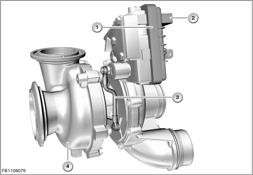
Index |
Explanation |
Index |
Explanation |
|---|---|---|---|
1 |
Charge-air pressure controller |
2 |
3-pin plug-in connection |
3 |
Adjusting lever |
4 |
Turbocharger |
The DDE provides the electric charge-air pressure controller with a pulse-width modulated signal. The operating range of the signal lies between 10 % and 95 %, whereby 10 % means 'guide vanes opened' and 95 % means 'guide vanes closed'.
The electronics in the charge-air pressure controller convert the PWM signal into an adjustment angle and activate the actuator motor. The charge-air pressure controller itself is self-diagnosable and reports faults to the DDE.
Structure and inner circuit
The charge-air pressure controller is connected by means of a 3-pin plug-in connection.
The charge-air pressure controller is supplied with voltage via terminal 15N.
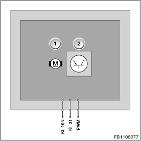
Index |
Explanation |
Index |
Explanation |
|---|---|---|---|
1 |
Electric motor |
2 |
Control electronics |
Pin assignments
Pin |
Explanation |
|---|---|
Kl. 15N |
Terminal 15, power supply |
Terminal 31 |
Ground connection |
PWM |
Pulse-width modulated activation of flow regulating valve |
Sectional view and target values
The variable turbine geometry makes it possible to adjust the flow cross section and flow direction to the turbine depending on the engine operating point. This adjustment enables the entire exhaust gas energy to be used, thus improving the efficiency of the exhaust turbocharger - and thus of the engine - compared to control with a wastegate valve.
The charge-air pressure controller adjusts the guide vanes. Adjustment of the guide vanes reduces the flow cross section and changes the flow direction. The flow rate of the exhaust gas increases, thus increasing the exhaust-gas pressure on the turbine wheel.
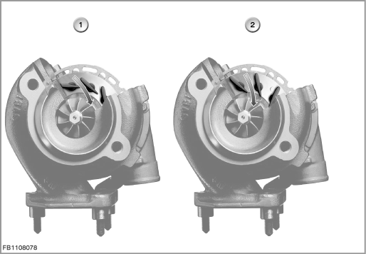
Index |
Explanation |
Index |
Explanation |
|---|---|---|---|
1 |
Guide vanes closed at lower engine speed |
2 |
Guide vanes opened at high engine speed |
Observe the following target values for the charge-air pressure controller:
Variable |
Value |
|---|---|
Power supply |
10.8 to 16 V |
Pulse duty factor of pulse width modulation |
5 to 95 % |
Frequency pulse width modulation |
276 to 324 Hz |
Output current |
8.4 to 9.7 mA |
Temperature range |
-40 to 130 °C |
Diagnosis instructions
Failure of the component
If the charge-air pressure controller fails, the following behaviour is to be expected:
- Fault memory entry in the engine control module
- Deactivation of charge-air pressure control
- Exhaust gas recirculation is deactivated
- In the event of a control deviation in the charge-air pressure, the fuel injection rate is limited and a substitute value is output for the charge-air pressure.
No liability can be accepted for printing or other faults. Subject to changes of a technical nature