Flow regulating valve and high-pressure pump
Flow regulating valve and high-pressure pump
The flow regulating valve is attached to the high-pressure pump (CP4.2). The flow regulating valve is a pulse-width modulated activated valve. With active volumetric flow regulation, the DDE activates the flow regulating valve with various pulse duty factors. The target pressure calculated by the DDE for the rail pressure is set.
The flow regulating valve regulates the flow of fuel from the low-pressure side into the high-pressure side of the high-pressure pump. This sets the desired rail pressure. The less fuel the flow regulating valve allows to flow into the high pressure side, the less the cylinders of the high-pressure pump are filled. The consequence is that less rail pressure is built up.
The high pressure pump constantly generates the system pressure in the rail. Two valves are used to control the required rail pressure:
- Flow regulating valve
- Rail-pressure regulating valve (see corresponding functional description)
Functional description
The right rail pressure is set depending on the operating point with one of the following 3 possible regulation options:
- Volumetric flow regulation by the flow regulating valve:
The flow regulating valve only allows the amount of fuel to flow into the high pressure pump from the low-pressure side that is required in order to generate the required fuel rail pressure. The high-pressure pump cylinder is not completely filled with fuel. The higher the control signal current, the lower is the rail pressure that is generated. The rail-pressure regulating valve is not supplied with current for the maximum pressure. The rail-pressure regulating valve is supplied with slightly higher current than would be necessary for setting the target pressure. - Pressure regulation by the rail pressure control valve:
The high pressure pump constantly delivers fuel at high pressure to the rail. The rail-pressure regulating valve hives off the excess volume of fuel from the rail into the return line. The higher the control signal current, the higher the rail pressure that is maintained. The flow regulating valve is set to maximum flow. - Combined simultaneous regulation by the rail-pressure regulating valve and flow regulating valve:
With very low fuel injection rates of less than approx. 4 mg (in the coast mode), it is necessary that the rail-pressure regulating valve hives off some fuel from the high-pressure system. The reason is that the high-pressure pump cannot run with zero delivery. This means that the high-pressure pump supplies fuel to the high-pressure system even when the flow regulating valve is closed. This would lead to excessive rail pressure and thus to a control deviation.
The two control methods are used under the following engine operating conditions:
- On engine start: Pressure regulation is always active.
- When the engine is running: At a coolant temperature below 1 °C, the pressure regulation is always active At a coolant temperature above 15 °C, the combined pressure regulation is always active
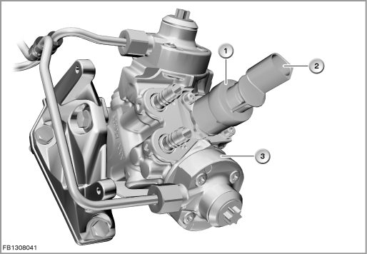
Index |
Explanation |
Index |
Explanation |
|---|---|---|---|
1 |
Flow regulating valve |
2 |
2-pin plug-in connection |
3 |
High-pressure pump (CP4.2) |
|
|
Structure and inner circuit
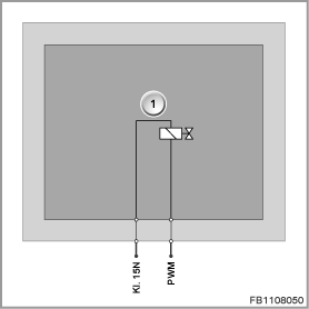
The flow regulating valve is connected by means of a 2-pin plug-in connection.
The flow regulating valve is supplied with voltage via terminal 15N.
Index |
Explanation |
Index |
Explanation |
|---|---|---|---|
1 |
Flow regulating valve |
|
|
Pin assignments
Pin |
Explanation |
|---|---|
Kl. 15N |
Terminal 15, power supply |
PWM |
Pulse-width modulated activation of flow regulating valve |
Sectional view and target values
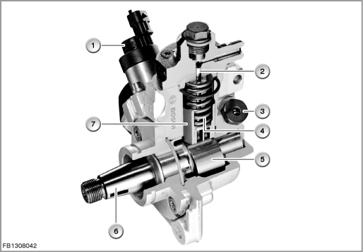
The high-pressure pump (CP4.2) has 2 plungers.
The high-pressure pump is located on the power-emitting side and is driven by the crankshaft via the timing chain. The high-pressure pump is able to generate a pressure of 2000 bar.
This means that the flow regulating valve determines the pressure generated by the pump and applied in the rail. In this way, the high-pressure pump does not generate any unnecessarily high pressure in part-load operation which then has to be lowered by the rail-pressure regulating valve. This reduces the drive power of the high-pressure pump, thus lowering fuel consumption of the engine.
Index |
Explanation |
Index |
Explanation |
|---|---|---|---|
1 |
Flow regulating valve |
2 |
Pistons |
3 |
Overflow valve |
4 |
Spring |
5 |
Double cams |
6 |
Drive shaft |
7 |
Tappet |
|
|
Observe the following target values for the flow regulating valve:
Variable |
Value |
|---|---|
Power supply |
12 Volts |
Pulse duty factor |
30 to 95 % |
Maximum output current |
1.4 A |
Temperature range |
-40 °C to 130 °C |
Diagnosis instructions
Failure of the component
If the flow regulating valve fails, the following behaviour is to be expected:
- Fault memory entry in the engine control module
- If activation of the flow regulating valve is interrupted or has a short circuit to ground, the flow regulating valve adjusts to full delivery. The DDE detects the fault, limits the fuel injection rate and switches to pressure regulation.
- In the event of a short circuit to positive, the engine shuts down.
No liability can be accepted for printing or other faults. Subject to changes of a technical nature