Exhaust gas temperature sensor before catalytic converter
Exhaust gas temperature sensor before catalytic converter
The exhaust gas temperature sensor is located directly beside the Lambda oxygen sensor on the joint housing for particle filter and oxidation catalytic converter. The exhaust gas temperature sensor is required for regeneration of the diesel particle filter.
Functional description
Under certain operation conditions, the throttle valve throttles the intake air. In combination with 1 to 2 post injections, this leads to an increase in the exhaust-gas temperature (regeneration of the diesel particle filter). The exhaust gas temperature sensor is used to control the exhaust-gas temperature during the cyclical regeneration.
A temperature-dependent electrical resistor is used for temperature detection. The circuit contains a power diplexer where the resistance can be measured depending on the temperature. This is converted into a temperature using a characteristic curve that is specific to the sensor.
A hot conductor (NTC) is installed in the exhaust gas temperature sensor; the resistance value of this hot conductor falls with rising temperature. The resistance changes depending on the temperature from 96 k to 32 , which corresponds to a temperature of -40 °C to 800 °C.
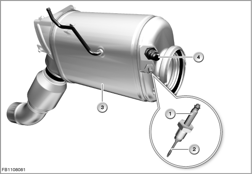
Index |
Explanation |
Index |
Explanation |
|---|---|---|---|
1 |
2-pin plug-in connection |
2 |
Exhaust gas temperature sensor |
3 |
Particle filter and oxidation catalytic converter |
4 |
Oxygen sensor |
Structure and inner circuit
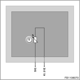
The exhaust gas temperature sensor is connected by means of a 2-pin plug-in connection.
The sensor is supplied with ground by the engine management system.
Index |
Explanation |
Index |
Explanation |
|---|---|---|---|
1 |
Charge-air-temperature sensor |
|
|
Pin assignments
Pin |
Explanation |
|---|---|
SIG |
Charge-air temperature signal |
Kl. 31E |
Terminal 31, electronics earth |
Characteristic curve and target values
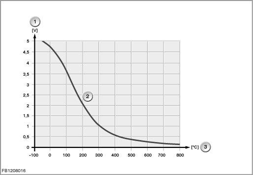
The resistance of the exhaust gas temperature sensor changes depending on the temperature from 96 k to 32 , which corresponds to a temperature of -40 °C to 800 °C.
Index |
Explanation |
Index |
Explanation |
|---|---|---|---|
1 |
Signal voltage |
2 |
Characteristic curve for hot conductor (NTC) |
3 |
Temperature |
4 |
|
Observe the following target values for the exhaust gas temperature sensor:
Variable |
Value |
|---|---|
Voltage range for exhaust gas temperature sensor |
0.15 to 4.95 Volts |
Response time |
Less than 25 s |
Resolution of exhaust-gas temperature |
approx. 1 °C |
Maximum output current |
10 mA |
Temperature range |
-40 °C to 800 °C |
Diagnosis instructions
Failure of the component
If the exhaust gas temperature sensor fails, the following behaviour is to be expected:
- Fault memory entry in the engine control module
No liability can be accepted for printing or other faults. Subject to changes of a technical nature