swirl flap actuator
swirl flap actuator
The swirl-flap actuator is attached to the intake air collector.
The swirl flaps are steplessly adjusted with an electric swirl-flap actuator.
The controllable swirl flaps are located in the tangential ports. Depending on the operating range, the swirl flaps are activated with various pulse duty factors. The further the swirl flaps are closed, the more fresh air is taken in exclusively through the swirl port. This increases the swirl of the fresh air that is taken in.
Functional description
In the lower load and engine speed range, the swirl flaps are variably closed depending on the operating range. The swirl flaps are fully opened under the following conditions:
- Engine speed greater than 2250 rpm
- Injection quantity (volume) greater than 30 mg/stroke
The position of the swirl flaps is also corrected depending on the ambient pressure. At ambient pressures of less than 880 hPa, the swirl flaps tend to open further.
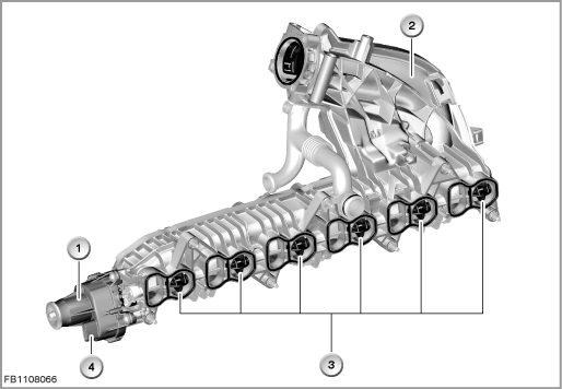
Index |
Explanation |
Index |
Explanation |
|---|---|---|---|
1 |
swirl flap actuator |
2 |
Intake air collector |
3 |
Swirl flaps |
4 |
5-pin plug-in connection |
The swirl-flap actuator has an adjustment range of 110°. The adjusting time across the entire adjustment range for opening or closing is approx. 0.1 seconds.
Structure and inner circuit
The actuator motor for the swirl-flap adjustment is a DC motor.
The position sensor is a Hall sensor. The Hall sensor determines the revolutions of the actuator motor. This is used to calculate the position of the swirl flaps.
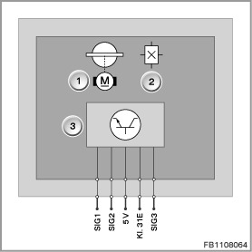
Index |
Explanation |
Index |
Explanation |
|---|---|---|---|
1 |
Swirl-flap actuator with swirl flap (6 flaps) |
2 |
Hall-effect sensor |
3 |
Electronic module with electronic evaluation unit |
|
|
Pin assignments
Pin |
Explanation |
|---|---|
SIG1 |
Activation of swirl-flap actuator, plus |
SIG2 |
Activation of swirl-flap actuator, minus |
5 V |
Power supply of swirl flap position sensor |
Kl. 31E |
Ground of swirl flap position sensor |
SIG3 |
Signal of swirl flap position sensor |
Schematic overview and target values
The position sensor for the swirl flaps is supplied with 5 Volts and ground by the DDE.
A bridge circuit (H bridge) is used to activate the actuator motor. This permits activation of the actuator motor in the opposite direction. The bridge circuit is monitored for diagnosis.
H bridge refers to an electrical gearshift where 5 shift elements are interconnected in the shape of the upper case letter H.
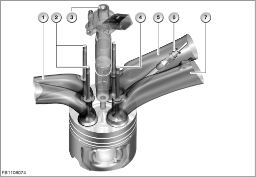
Index |
Explanation |
Index |
Explanation |
|---|---|---|---|
1 |
Exhaust ports |
2 |
Exhaust valves |
3 |
Injectors |
4 |
Inlet valves |
5 |
Swirl port |
6 |
Glow plug |
5 |
Tangential port |
|
|
Observe the following target values for the swirl-flap actuator:
Variable |
Value |
|---|---|
Power supply of actuator motor |
12 Volts |
Activation frequency for actuator motor |
1300 Hz |
Current consumption of actuator motor |
1.3 A |
Power supply of swirl flap position sensor |
4.8 to 5.2 V |
Current consumption of swirl flap position sensor |
16 mA |
Temperature range of swirl flap position sensor and actuator motor |
-40 °C to 130 °C |
Diagnosis instructions
Failure of the component
If the position sensor fails, the following behaviour is to be expected:
- Fault memory entry in the engine control module
- Emergency operation with substitute value
If the actuator motor fails, the following behaviour is to be expected:
- Fault memory entry in the engine control module
- Mechanical emergency air position of the swirl flap
General information
If the swirl-flap actuator is replaced, the following service function must be run before the replacement:
- Adaptation of swirl-flap actuator
No liability can be accepted for printing or other faults. Subject to changes of a technical nature