Short-range sensor, left
Short-range sensor, left
For the active cruise control (ACC) with Stop & Go function, 2 identical short-range sensors are installed. The sensors are mounted on the front bumper bracket by means of a plastic bracket (invisible behind the bumper).
The short-range sensors assume the following tasks:
- Sensing objects in the short range from approx. 2 to 24 metres ahead of the vehicle
- Calculating position and movement data
- Outputting a list of these calculated data to the Integrated Chassis Management (ICM)
In some markets (e.g. Japan), ACC is offered without the Stop&Go function due to approval restrictions.
Functional description
The short-range sensor is a radar sensor.
The short-range sensor picks up vehicles and objects at the side of the road in a comparatively wide cone. However, the cone only reaches a distance of approx. 20 metres.
The short-range sensors describe each sensed object with the following attributes:
- Distance
- Lateral position
- Relative speed
The attributes are summarized in a list and made available for further processing to the ICM on a separate bus, the sensor CAN (S-CAN).
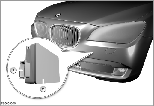
Index |
Explanation |
Index |
Explanation |
|---|---|---|---|
1 |
6-pin plug-in connection |
2 |
Short-range sensor |
The short-range sensors are supplied with voltage by the distribution box in the junction box (terminal 15N). The sensors are not connected to the wake-up line. The Integrated Chassis Management (ICM) wakes up the short-range sensors by means of corresponding messages via the S-CAN.
The short-range sensors are intelligent sensors that monitor their own operability. Any fault states that occur are stored in the ICM.
The short-range sensors cannot be activated directly via the BMW diagnosis system.
Structure and inner circuit
The short-range sensor consists of:
- Housing
- Transmit channels: emission of radar beams
- Receive channel: reception of the radar beams
- Electronic evaluation unit
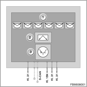
Index |
Explanation |
Index |
Explanation |
|---|---|---|---|
1 |
Transmit channels |
2 |
Receive channel |
3 |
Electronic module with electronic evaluation unit |
|
|
Pin assignments
Pin |
Explanation |
|---|---|
Terminal 31 |
Ground connection |
S-CAN H |
Sensor CAN High |
S-CAN L |
Sensor CAN Low |
Terminal 15N |
Power supply |
Terminal 31 |
Earth connection: used for left-hand short-range sensor (coding left) |
Terminal 31 |
Earth connection: not used for right-hand short-range sensor |
In the wiring harness, pin 5 is set to ground for the left-hand sensor and pin 6 is set to earth for the right-hand sensor. This means that the installation location is encoded, which must be taken into account in the calculation of the object data.
Control curve and target values
For the full functionality of the active cruise control with Stop & Go function, an additional long-range sensor is necessary.
The measured values of all 3 sensors result in the following control curve:
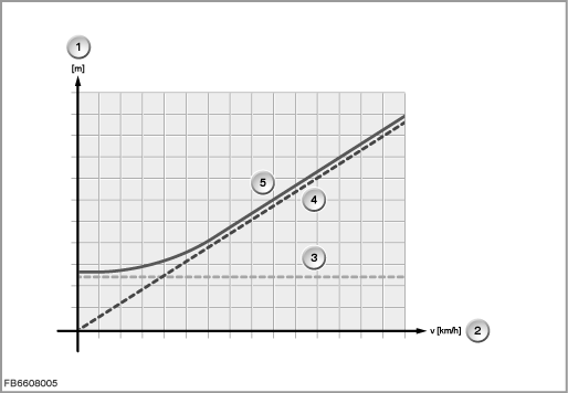
Index |
Explanation |
Index |
Explanation |
|---|---|---|---|
1 |
Target distance in metres |
2 |
Driving speed in km/h |
3 |
Target distance, proportion at a standstill, constant |
4 |
Target distance, proportion during driving, proportional to driving speed |
5 |
Resulting target distance from proportions of driving and standstill |
|
|
Observe the following target values for the short-range sensor:
Variable |
Value |
|---|---|
Power supply |
9 to 16 Volts |
Horizontal opening angle |
±60° |
Vertical opening angle |
±20° |
Mean transmission frequency |
24 GHz |
Transmission power |
approx. 0.08 mW (average value) |
Temperature range |
-40 °C to 80 °C |
Maximum current consumption |
500 mA |
Diagnosis instructions
Failure of the component
If the short-range sensor fails, the following behaviour is to be expected:
- Fault memory entry in the ICM
- No control operation for ACC in the short range
- Output of a Check Control message in the instrument cluster
General information
Note! Replacement of the short-range sensor.
On replacement of a short-range sensor, observe the exact installation location: in accordance with the repair instructions. A setting similar to the long-range sensor is not necessary.
Instead, the installation angle of the sensor in the ICM must be stored again: Use the corresponding service function.
Service functions
Observe the following service functions:
Service functions -> Chassis -> Active cruise control -> Set long-range sensor
Service functions -> Chassis -> Active cruise control -> Set short-range sensors
No liability can be accepted for printing or other faults. Subject to changes of a technical nature