Evaporator temperature sensor
Evaporator temperature sensor
The evaporator temperature sensor picks up the outlet temperature of the cooled air at the evaporator to prevent freezing of the evaporator.
The evaporator plates are cooled by the refrigerant that has been evaporated inside the evaporator. The airflow generated by the blower is fed over the cooled evaporator plates. The air is cooled and dried and guided into the vehicle interior.
The evaporator temperature is regulated with the help of the evaporator temperature sensor and a controllable expansion valve. The evaporator temperature is set to the predefined specification of 2 °C. Lower temperatures are not possible due to the risk of icing.
If the ”variable evaporator control” function has been encoded, the nominal evaporator temperature is calculated between 2 and 8 °C. The specification depends on the ambient temperature, the ventilation temperature and the refrigerant pressure.
A variable evaporator temperature reduces dehumidification. This reduces the risk of mucous membranes drying out.
The evaporator temperature sensor is directly connected to the IHKA control module (”IHKA” stands for ”integrated automatic heating and air conditioning system”).
If the evaporator temperature falls below a specified target value (2 °C), the IHKA control module switches the A/C compressor off (only on vehicles without a rear air conditioner).
Vehicles with rear air conditioner
On vehicles with automatic rear air conditioning (HKA), the A/C compressor is not switched off. If the evaporator of the IHKA appears about to freeze over, the IHKA control module sends a message in the K-CAN. The HKA control module receives the message and supplies current to the front shut-off valve integrated in the expansion valve. This closes the expansion valve and switches off the front refrigerant circuit.
Functional description
The evaporator temperature sensor is a hot conductor or NTC resistor (”NTC” stands for ”Negative Temperature Coefficient”).
The hot conductor means that the variable ”temperature” can be converted into the variable ”resistance” which can be electrically evaluated.
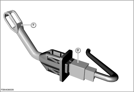
Index |
Explanation |
Index |
Explanation |
|---|---|---|---|
1 |
Evaporator temperature sensor |
2 |
2-pin plug-in connection |
The current-conducting materials in the hot conductor conduct current better at high temperatures than at low temperatures. That means: With rising temperatures, the resistance falls.
Structure and inner circuit
In order to balance out internal temperature effects, the hot conductor is operated with low current. This means that the outer ambient temperature is decisive for the resistance value.
Each temperature change on the hot conductor leads to a change in the voltage signal.
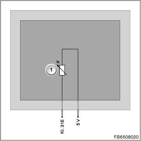
Index |
Explanation |
Index |
Explanation |
|---|---|---|---|
1 |
Hot conductor |
|
|
Pin assignments
Pin |
Explanation |
|---|---|
Kl. 31E |
Terminal 31, electronics earth |
5 V |
5 Volts, power supply |
Characteristic curve and target values
The evaporator temperature sensor is supplied with 5 Volts by the IHKA control module. The logarithmic characteristic curve of the evaporator temperature sensor must be linearized by the microprocessor in the IHKA control module. The actual temperature is then determined by means of interpolation between defined corner points.
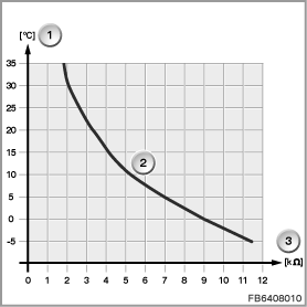
Index |
Explanation |
Index |
Explanation |
|---|---|---|---|
1 |
Temperature in degrees Celsius (°C) |
2 |
Characteristic curve for evaporator temperature sensor |
3 |
Resistance in Kiloohms (k) |
|
|
Observe the following target values for the evaporator temperature sensor:
Variable |
Value |
|---|---|
Voltage range |
4.5 to 5.5 V |
Maximum current consumption |
10 mA |
Temperature range |
-5 to 60 °C |
Diagnosis instructions
Failure of the component:
If the evaporator temperature sensor fails, the following behaviour is to be expected:
- Vehicles without automatic rear air conditioning
- Fault memory entry in the IHKA control module
- Substitute value from the IHKA control module: Less than 0 °C
On the basis of the low substitute value, the IHKA control module no longer activates the A/C compressor.
- Fault memory entry in the IHKA control module
- Vehicles with automatic rear air conditioning (HKA)
- Fault memory entry in the IHKA control module
- Substitute value from the IHKA control module: Less than 0 °C
On the basis of the low substitute value, the front shut-off valve integrated in the expansion valve is supplied with current via the HKA control module. This closes the front expansion valve and switches off the front refrigerant circuit.
The refrigerant circuit for the rear air conditioner remains functional.
- Fault memory entry in the IHKA control module
- Fault message:
- Short circuit to ground:
for example, resistance range less than 1.6 k. - Short circuit to positive or open line:
for example, resistance range greater than 12 k.
- Short circuit to ground:
No liability can be accepted for printing or other faults. Subject to changes of a technical nature