Roof air vent, left
Roof air vent, left
The left roof air vent is only installed in conjunction with the rear air conditioner.
A total of 2 roof air vents are installed (due to left-right separation).
The following electrical components are installed in roof air vent:
- LED for locating light
- Roof air vent temperature sensor
The left roof air vent temperature sensor is used to measure the delivery temperature in the left roof air vent.
The cold air from the evaporator and the warm air coming from the luggage compartment are distributed according to the position of the air distribution flap motor. The position of the stratification flap mixes the air. Every change to the delivery temperature at the roof air vent caused by a change in the flap position is determined by the temperature sensor positioned in the air flow.
The signal from the roof air vent temperature sensor is evaluated in the operating unit of the right automatic rear air conditioning (right HKA operating unit), digitized and sent across the bus to the HKA control module. The HKA control module evaluates this information and activates the left air distribution flap motor and the left mixed-air flap motor.
Functional description
The roof air vent temperature sensors are hot conductors or NTC resistors (”NTC” stands for ”Negative Temperature Coefficient”).
The hot conductor means that the variable ”temperature” can be converted into the variable ”resistance” which can be electrically evaluated. The current-conducting materials in the hot conductor conduct current better at high temperatures than at low temperatures. That means: With rising temperatures, the resistance falls.
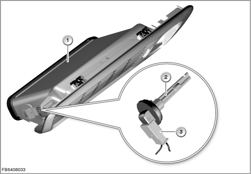
Index |
Explanation |
Index |
Explanation |
|---|---|---|---|
1 |
Roof air vent |
2 |
Roof air vent temperature sensor |
3 |
Plug-in connection for temperature sensor |
|
|
Structure and inner circuit
The left roof air vent is connected to the vehicle network by means of a 6-pin plug-in connection.
The locating light (terminal 58g) in the roof air vent is supplied with voltage and ground via the left HKA operating unit. The locating light is controlled by the footwell module (FRM).
The signal line of the left roof air vent temperature sensor is directly connected to the right HKA operating unit.
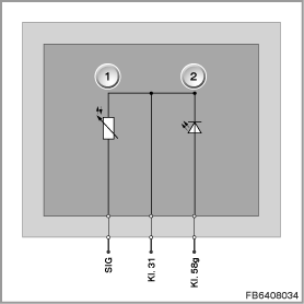
Index |
Explanation |
Index |
Explanation |
|---|---|---|---|
1 |
Roof air vent temperature sensor |
2 |
Locating light (LED) |
Pin assignments
Pin |
Explanation |
|---|---|
Kl. 58g |
Terminal 58g, locating light |
Kl. 31 |
Terminal 31 |
SIG |
Signal line and power supply for roof air vent temperature sensor |
Characteristic curve and target values
Roof air vent temperature sensor
Each change to the roof air vent temperature sensor leads to a change in the resistance signal. The evaluation takes place in the HKA control module.
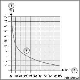
Index |
Explanation |
Index |
Explanation |
|---|---|---|---|
1 |
Temperature in degrees Celsius (°C) |
2 |
Characteristic curve for hot conductor |
3 |
Resistance in Kiloohms (k) |
|
|
Observe the following target values for the left roof air vent temperature sensor:
Variable |
Value |
|---|---|
Power supply |
5 V |
Temperature range |
-40 to 85 °C |
Resistance range (measuring range) |
1.2 to 100 k |
Diagnosis instructions
Failure of the component:
Roof air vent temperature sensor
If the roof air vent temperature sensor fails, the following behaviour is to be expected:
- Fault memory entry in the HKA control module
- Substitute value from the HKA control module: 20 °C
No liability can be accepted for printing or other faults. Subject to changes of a technical nature