Front centre ventilation grille
Front centre ventilation grille
The design of the front centre ventilation grille depends on the climate control that is installed.
- Integrated automatic heating and air-conditioning system (IHKA Basic)
The following electrical components are installed in the ventilation grille:- LED for locating light
- Left stratification control
- Right stratification control
- LED for locating light
- Integrated automatic heating and air-conditioning system with high equipment (IHKA High)
The following electrical components are installed in the front centre ventilation grille:- LED for locating light
- Left stratification control
- Right stratification control
- Left limit-position switch
- Right limit-position switch
On the basis of this information, the IHKA control module activates the 2 front stratifying-flap motors (left and right).
With the help of the limit-position switches, the ventilation flaps in the front centre ventilation grille pick up the following positions:- Ventilation flaps open (contact in the limit-position switch closed)
- Ventilation flaps closed (contact in the limit-position switch open)
- LED for locating light
Functional description
The stratification controls have a linear resistance value dependent on the angle of rotation.
The limit-position switches are switched on and off mechanically via eccentric washers.
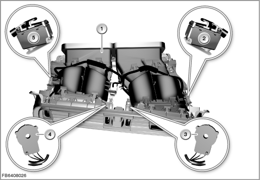
Index |
Explanation |
Index |
Explanation |
|---|---|---|---|
1 |
Front centre ventilation grille |
2 |
Right limit-position switch |
3 |
Right stratification control |
4 |
Left stratification control |
5 |
Left limit-position switch |
|
|
Structure and inner circuit
The centre ventilation grille is connected to the vehicle network by means of a 10-pin plug-in connection.
The locating light in the front centre ventilation grille is controlled via the footwell module (FRM).
The stratification controls are supplied with voltage and ground by the IHKA control module.
Front centre ventilation grille of the IHKA Basic
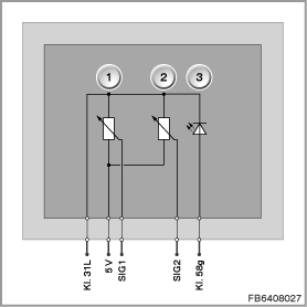
Index |
Explanation |
Index |
Explanation |
|---|---|---|---|
1 |
Left stratification control |
2 |
Right stratification control |
3 |
Locating light (LED) |
|
|
Pin assignments
Pin |
Explanation |
|---|---|
Terminal 58g |
Terminal 58g, locating light |
Terminal 31L |
Terminal 31, load ground |
5 Volts |
Power supply |
SIG1 |
Left stratification control signal line |
SIG2 |
Right stratification control signal line |
Front centre ventilation grille of the IHKA High
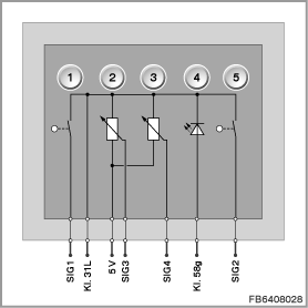
Index |
Explanation |
Index |
Explanation |
|---|---|---|---|
1 |
Left limit-position switch |
2 |
Left stratification control |
3 |
Right stratification control |
4 |
Locating light (LED) |
5 |
Right limit-position switch |
|
|
Pin assignments
Pin |
Explanation |
|---|---|
Terminal 58g |
Terminal 58g, locating light |
Terminal 31L |
Terminal 31, load ground |
5 Volts |
Power supply |
SIG1 |
Left limit-position switch signal line |
SIG2 |
Right limit-position switch signal line |
SIG3 |
Left stratification control |
SIG4 |
Right stratification control |
Characteristic curve and target values
Stratification controls
Each manual change to the stratification control leads to a change in the resistance signal. The evaluation takes place in the IHKA control module. The value is registered as a percentage (%).
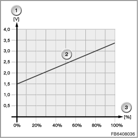
Index |
Explanation |
Index |
Explanation |
|---|---|---|---|
1 |
Voltage characteristics in Volts (V) |
2 |
Characteristic curve for stratification controls |
3 |
Adjusting path of the stratification control as a percentage (%) |
|
|
Observe the following target values for the stratification control:
Variable |
Value |
|---|---|
Power supply |
5 V |
Range of rotation |
approx. 60° |
Voltage in end position, fresh air |
1.5 ± 0.1 V |
Value in end position, fresh air as a percentage |
0 + 5 % or 0 % |
Voltage in end position, warm air |
3.4 ± 0.1 V |
Value in end position, warm air as a percentage |
100 + 0 % or - 5 % |
Temperature range |
-40 to 85 °C |
Diagnosis instructions
Failure of the component:
Limit-position switches
If a limit-position switch fails, the following behaviour is to be expected:
- No air emerges from the corresponding side of the ventilation grille
Stratification controls
If a stratification control fails, the following behaviour is to be expected:
- Fault memory entry in the IHKA control module
- Substitute value from the IHKA control module: 50 %
No liability can be accepted for printing or other faults. Subject to changes of a technical nature