Outside temperature sensor
Outside temperature sensor
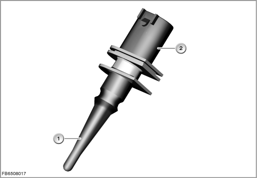
The outdoor temperature sensor is installed at the front end of the vehicle. The sensor picks up the outside temperature for all systems in the vehicle that require the outside temperature.
The signal of the outdoor temperature sensor is processed in the instrument cluster (KOMBI). The instrument cluster sends the message on the CAN bus and MOST bus (”CAN” stands for ”Controller Area Network” and ”MOST” stands for ”Media Oriented System Transport”).
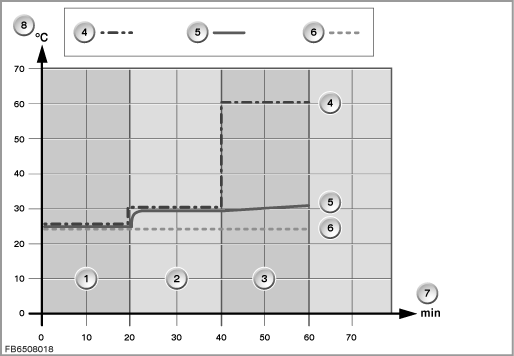
The instrument cluster sends an attenuated outside temperature value. That means: With the aid of a calculation model in the instrument cluster, the effect of the waste heat from the engine compartment on the temperature signal of the outdoor temperature sensor is attenuated. The increase in temperature is delayed.
The input variables for the calculation model are:
- Road speed
- Coolant temperature
- Engine status ON or OFF
- Outside temperature
A drop in the outside temperature is adopted and not damped. Reason: The engine and body cannot be colder than the ambient temperature.
During normal operation, the outside temperature is periodically calculated every second.
After terminal 15 OFF, the outside temperature is calculated periodically every 20 minutes for a maximum of 24 hours.
The outside temperature value is displayed on the LCD display in the instrument cluster.
Note: Under certain circumstances, an incorrect display of the outside temperature is physically unavoidable.
With certain driving profiles, the display deviates from the real value due to damping. In case of customer complaint, this characteristic has to be explained as being the current technical standard.
Example of damping the outside temperature:
Motorway driving, subsequent city traffic, the traffic jam
Index |
Explanation |
Index |
Explanation |
|---|---|---|---|
1 |
20 minutes motorway driving, roadspeed greater than 80 km/h |
2 |
20 minutes urban traffic, roadspeed greater than 40 km/h |
3 |
20 minutes stationary traffic, roadspeed 0 km/h |
4 |
Measured value of the outdoor temperature sensor |
5 |
Outside temperature display in the instrument cluster |
6 |
Real outside temperature |
7 |
Time in minutes (min) |
8 |
Temperature in degrees Celsius (°C) |
Functional description
The outdoor temperature sensor is a hot conductor or NTC resistor (”NTC” stands for ”Negative Temperature Coefficient”).
The hot conductor means that the variable ”temperature” can be converted into the variable ”resistance” which can be electrically evaluated.
Index |
Explanation |
Index |
Explanation |
|---|---|---|---|
1 |
Outside temperature sensor |
2 |
2-pin plug-in connection |
The current-conducting materials in the hot conductor conduct current better at high temperatures than at low temperatures. That means: With rising temperatures, the resistance falls.
Structure and inner circuit
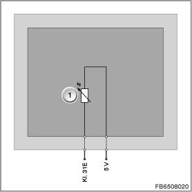
In order to balance out internal temperature effects, the hot conductor is operated with low current. This means that the outer ambient temperature is decisive for the resistance value.
Each temperature change on the hot conductor leads to a change in the voltage signal.
Index |
Explanation |
Index |
Explanation |
|---|---|---|---|
1 |
Hot conductor |
|
|
Pin assignments
Pin |
Explanation |
|---|---|
5 V |
5 Volts, power supply |
Kl. 31E |
Terminal 31, electronics ground |
Characteristic curve and target values
The outdoor temperature sensor is supplied with 5 Volts by the instrument cluster (KOMBI).
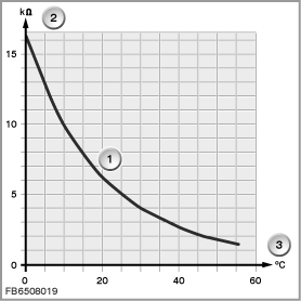
The logarithmic characteristic curve of the outdoor temperature sensor must be linearized by the microprocessor in the instrument cluster. The actual temperature is then determined by means of interpolation between defined corner points.
Index |
Explanation |
Index |
Explanation |
|---|---|---|---|
1 |
Characteristic curve for outdoor temperature sensor |
2 |
Resistance in Kiloohms (k) |
3 |
Temperature in degrees Celsius |
|
|
Observe the following target values for the outdoor temperature sensor:
Variable |
Value |
|---|---|
Power supply |
5 V |
Temperature range |
-40 to 50 °C |
Resistance range (measuring range) |
1.7 to 174 k |
Resolution of the display |
0.5 °C |
Diagnosis instructions
Failure of the component:
If the outdoor temperature sensor fails, the following behaviour is to be expected:
- Fault memory entry in the instrument cluster (KOMBI)
- Substitute value from the instrument cluster:
- In the event of failure of the sensor due to short circuit to ground:
for example 50 °C - In the event of failure of the sensor due to short circuit to positive or open line:
for example -40 °C
- In the event of failure of the sensor due to short circuit to ground:
After deletion of the fault memory, the instrument cluster outputs the current outside temperature value unattenuated or unfiltered to the equipment attached to the bus.
No liability can be accepted for printing or other faults. Subject to changes of a technical nature