Crankshaft sensor
Crankshaft sensor
The crankshaft sensor is attached to the transmission case.
The crankshaft sensor records the position of the crankshaft with the aid of an increment gear screwed to the crankshaft. The engine management system uses this to calculate the engine speed. The crankshaft sensor and camshaft sensor are necessary for the fully sequential injection system (fuel injection takes place individually for each cylinder at the specific point of ignition).
The signal from the crankshaft sensor means that the engine management system also evaluates the crankshaft acceleration. The crankshaft acceleration provides an indication of the combustion quality of individual cylinders.
Functional description
The increment gear has 58 teeth as well as a reference gap of 2 teeth.
The reference gap enables detection of the upper dead centre of the 1st cylinder. By monitoring the individual teeth, the Hall sensor delivers a certain number of signal jumps to the engine management system.
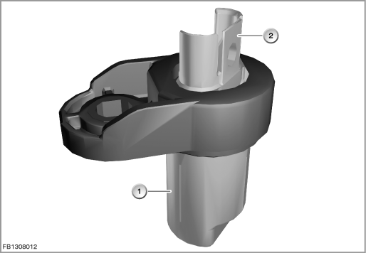
Index |
Explanation |
Index |
Explanation |
|---|---|---|---|
1 |
Crankshaft sensor |
2 |
3-pin plug-in connection |
The engine control module uses the scanned tooth flanks to calculate the duration as well as the length of a crankshaft revolution.
The time the increment gear requires to rotate past the Hall sensor is referred to as the crankshaft revolution per time.
For starting the engine, the engine control module checks the following conditions:
- fault-free signal from the crankshaft sensor and camshaft sensor
- both signals must be detected in a specific chronological sequence
This process is referred to as synchronization and is only performed when the engine is started. The synchronization enables the engine control module to activate the fuel injection correctly.
Without synchronization, no engine start is possible.
If the crankshaft sensor signals fails (with the 1st crankshaft revolution) or an invalid synchronization is detected for the engine start, the diagnosis starts immediately. Here, the camshaft sensor signals are read. If 12 flanks on the camshaft are read and the fault is still there, a fault is stored.
As soon as no crankshaft sensor signals are received or there is no valid synchronization with the engine running, debouncing starts.
Structure and inner circuit
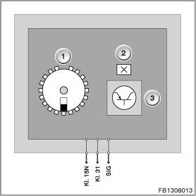
The measurement procedure is based on Hall IC. The Hall sensor is magnetically pretensioned by a permanent magnet.
The Hall IC delivers an output voltage proportionate to the magnetic field.
Index |
Explanation |
Index |
Explanation |
|---|---|---|---|
1 |
Increment gear |
2 |
Hall-effect sensor |
3 |
Electronic evaluation unit |
|
|
Pin assignments
Pin |
Explanation |
|---|---|
Kl. 15N |
Terminal 15N, power supply |
Kl. 31 |
Terminal 31, ground |
SIG |
Signal line |
Characteristic curve and target values
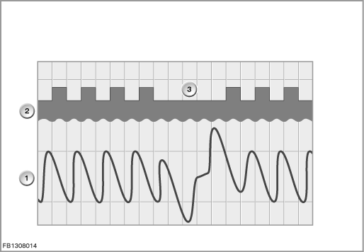
The transition from a high to a low phase is signalled by a falling tooth flank. In the engine management system, only the falling tooth flanks are counted. The difference between 2 falling tooth flanks is 6° crankshaft angle.
Index |
Explanation |
Index |
Explanation |
|---|---|---|---|
1 |
Signal path (calculated internally) |
2 |
Increment gear |
3 |
Tooth gap |
|
|
Observe the following target values for the crankshaft sensor:
Variable |
Value |
|---|---|
Voltage range |
6 to 16 Volts |
Engine speed range |
up to 8000 rpm |
Air gap range |
0.1 to 1.8 mm |
Maximum output current |
20 mA |
Outside temperature |
-40 °C to 160 °C |
Diagnosis instructions
Failure of the component
If the crankshaft sensor fails, the following behaviour is to be expected:
- Fault memory entry in the engine control module
- Emergency operation with substitute value
No liability can be accepted for printing or other faults. Subject to changes of a technical nature