Heating wire air mass flow sensor
Heating wire air mass flow sensor
The heating wire air mass flow sensor (Hitachi) is attached to the fresh air pipe after the intake muffler.
The heating wire air mass flow sensor is a combined sensor.
The heating wire air mass flow sensor picks up the actual air mass regardless of the air pressure. The air mass serves as a measurement variable in the DDE control module for the following functions:
- Calculation of the limitation quantity for fuel
- Exhaust gas recirculation control
An intake air temperature sensor is integrated in the heating wire air mass flow sensor. This sensor measures the temperature of the intake air before the exhaust turbocharger.
Functional description
An electrically heated platinum wire protrudes into the air flow. The temperature of the platinum wire is always kept constant. The air flow draws heat from the platinum wire. The greater the air-mass flow the more energy must be deployed to keep the temperature of the platinum wire constant.
A labyrinth ensures that only the actual air mass is detected. Return flows and pulsations are not detected due to the labyrinth.
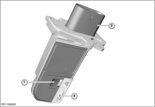
Index |
Explanation |
Index |
Explanation |
|---|---|---|---|
1 |
Heating wire air mass flow sensor |
2 |
5-pin plug-in connection |
3 |
Intake air temperature sensor |
|
|
Structure and inner circuit
The heating wire air mass flow sensor is supplied by the junction box with terminal 15N (vehicle voltage).
Note! Difference to hot-film air-mass sensor.
The heating wire air mass flow sensor has no controllable ground. With the engine at a standstill and terminal 15 On (e.g. automatic engine start-stop function), the heating wire air mass flow sensor is supplied with current. In contrast to the hot-film air-mass sensor, no oil and dirt residues are burned in. Reason: The heating wire is configured for significantly higher temperatures.
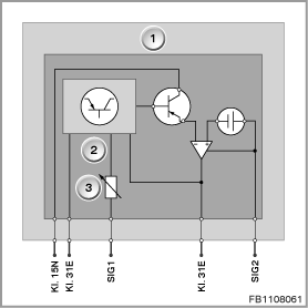
Index |
Explanation |
Index |
Explanation |
|---|---|---|---|
1 |
Heating wire air mass flow sensor |
2 |
Electronic evaluation unit |
3 |
Intake air temperature sensor |
|
|
Pin assignments
Pin |
Explanation |
|---|---|
Kl. 15N |
Terminal 15N, power supply |
Kl. 31E |
Terminal 31, electronics ground 1 |
SIG1 |
Intake air temperature signal |
Kl. 31E |
Terminal 31, electronics ground 2 |
SIG2 |
Air mass signal (pulse-width modulated) |
Signal path and target values
The electronic evaluation unit digitizes the signal of the heating wire air mass flow sensor. This signal is then transferred pulse-width modulated to the DDE control module. The signal quality for the air mass is temperature-dependent. High accuracy is required to precisely determine the air mass. This is why the air mass signal received in the engine control module must be corrected with the signal of the intake air temperature sensor.
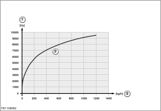
Index |
Explanation |
Index |
Explanation |
|---|---|---|---|
1 |
Output frequency |
2 |
Characteristic curve of heating wire air mass flow sensor |
3 |
Air mass |
|
|
Observe the following target values for the heating wire air mass flow sensor:
Variable |
Value |
|---|---|
Power supply |
13.4 to 13.6 V |
Sensor voltage |
4.9 to 5.1 V |
Maximum current consumption for heating wire air mass flow sensor |
15 mA |
Frequency range of heating wire air mass flow sensor |
1 to 9.5 kHz |
Measuring range of intake-air temperature |
-40 °C to 110 °C |
Temperature range |
-40 °C to 120 °C |
Diagnosis instructions
Failure of the component
If the heating wire air mass flow sensor fails, the following behaviour is to be expected:
- Fault memory entry in the engine control module
- Emergency operation with substitute value
General information
In normal operation, the air mass flow meter is subject to effects such as soiling and ageing. These effects cause divergence between the stored characteristic and the specified status resulting in lack of power or black smoke. In order to prevent the effects of this problem, the heating wire air mass flow sensor adaptation has been introduced.
The service function 'Mass air flow meter adaptation' must be run if the mass air flow meter is replaced. The stored compensation factors are reset to 0 in the process.
No liability can be accepted for printing or other faults. Subject to changes of a technical nature