Oxygen sensor behind catalytic converter
Oxygen sensor behind catalytic converter
The monitor sensor with non-sequential characteristic curve is a jump sensor made by Bosch, type LSF 4.2.
This monitor sensor is used after the catalytic converter for catalytic converter diagnosis. The monitor sensor reliably detects deviations from Lambda value = 1, but cannot determine the extent of the deviation in the mixture.
Functional description
The front oxygen sensor continuously measures the residual oxygen in the exhaust gas. The fluctuation values of the residual oxygen are forwarded to the engine control module as a current signal. The DME corrects the fuel trim composition by means of fuel injection.
A second oxygen sensor (monitoring sensor) is built in behind the catalytic converter. The catalytic converter has a high oxygen accumulation capability. This means there is only a little air behind the catalytic converter. The monitoring sensor supplies a virtually constant (attenuated) voltage. With increasing age, the oxygen accumulation capability of the catalytic converter declines. The control sensor then reacts increasingly to oxygen sensor deviation with voltage fluctuations. These characteristics are used by a special diagnosis function for catalytic converter monitoring. A malfunction of the catalytic converter is indicated by the emissions warning lamp.
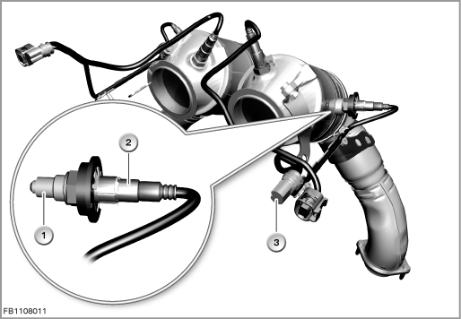
Index |
Explanation |
Index |
Explanation |
|---|---|---|---|
1 |
Oxygen sensor |
2 |
Housing |
3 |
4-pin plug-in connection |
|
|
As the exhaust gas also still contains residual oxygen when the engine is operate with a rich mixture, an electrical voltage occurs between the outer electrode and the inner electrode. So that the reference variable always remains the same, the reference air port is connected to the ambient air. The reference variable is thus the oxygen content of the ambient air.
Structure and inner circuit
A protective coat prevents damage from arising on the outer electrode due to residues in the exhaust gas. This ceramic layer made of zirconium dioxide (ZrO2) conducts oxygen ions as of approx. 350 °C.
A heating element is integrated to ensure that the Lambda oxygen sensor reaches operating temperature as quickly as possible.
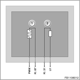
Index |
Explanation |
Index |
Explanation |
|---|---|---|---|
1 |
Oxygen sensor heating |
2 |
Measurement cell |
Pin assignments
Pin |
Explanation |
|---|---|
PWM |
Pulse-width modulated activation of the oxygen sensor heating |
Kl. 87 |
Battery voltage, terminal 15 on |
Kl. 31 |
Ground at measurement cell |
U1 |
Voltage at measurement cell |
Signal path and target values
The residual oxygen content, which corresponds to a fuel trim composition of Lambda value = 1, means that the voltage measurement at the measurement cell shows a voltage of 450 Millivolts. At Lambda value = 1, the composition of the emissions with various substances is ideal.
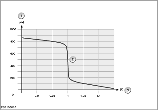
Index |
Explanation |
Index |
Explanation |
|---|---|---|---|
1 |
Voltage at measurement cell |
2 |
Signal path |
3 |
Lambda |
|
|
Observe the following target values for the monitor sensor:
Variable |
Value |
|---|---|
Voltage range of oxygen sensor heating |
10.7 to 16.5 V |
Voltage of oxygen sensor heating warming phase |
4 V |
Operating temperature |
≥ 350 °C |
Heater resistor at 20 °C |
9 ±2 |
Maximum pump current |
2.2 to 2.6 |
Diagnosis instructions
Failure of the component
If the monitor sensor fails, the following behaviour is to be expected:
- Fault memory entry in the engine control module
- The emissions warning lamp lights up in the instrument cluster
General information
The following monitoring functions of the diagnosis check the state of the engine and of the exhaust system:
- Lambda adaptation
Lambda adaptation (fuel mixture adaptation) serves the purpose of compensating for component tolerances that influence the mixture and ageing effects. - Catalytic converter diagnosis
The diagnosis check the oxygen accumulation capability of the catalytic converter. The oxygen accumulation capability is a measurement for the conversion capability of the catalytic converter.
Important! Protect the plug-in connection against soiling.
The monitor sensor requires ambient air inside the sensor. The ambient air enters the interior via the plug-in connection through the cable. This is why the plug-in connection must be protected against soiling, e.g. by wax or preserving agent. In the event of faults in the oxygen sensor control, the plug-in connection on the broadband oxygen sensor must be checked for soiling.
No liability can be accepted for printing or other faults. Subject to changes of a technical nature