Camshaft sensor
Camshaft sensor
The camshaft sensor is attached to the cylinder head cover.
The camshaft sensor uses an increment gear (camshaft sensor wheel) attached to the camshaft to detect the position of the intake camshaft.
If the crankshaft sensor fails, the engine management system uses this to calculate the engine speed.
The camshaft sensor and the crankshaft sensor are required for fuel injection (fuel injection individually for each cylinder, optimized at the point of ignition).
Functional description
The camshaft sensor enables the engine management system to detect whether the 1st cylinder is in the compression phase or charge cycle phase.
The camshaft sensor is designed as a non-contact Hall sensor.
The camshaft sensor wheel has 6 different flank spacings. The flank spacings are detected by the Hall sensor.
The engine management system uses these to calculate: here
- Camshaft rotational speed
- Camshaft speed
- Exact position of the camshaft
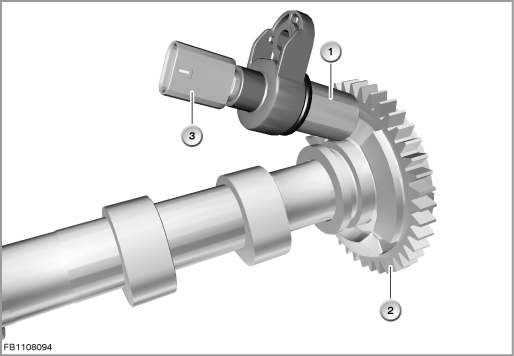
Index |
Explanation |
Index |
Explanation |
|---|---|---|---|
1 |
Camshaft sensor |
2 |
Intake camshaft |
3 |
3-pin plug-in connection |
|
|
For starting the engine, the engine control module checks the following conditions:
- Error-free signal from the crankshaft sensor
- both signals must be detected in a specific chronological sequence
This process is referred to as synchronization and is only performed when the engine is started. The synchronization enables the engine control module to activate the fuel injection correctly.
Without synchronization, no engine start is possible.
When voltage is applied, it is detected whether the sensor is above a tooth or above a gap.
Structure and inner circuit
The measurement procedure is based on Hall IC. The output signal has the status Low above a flank and the status High above a gap.
The camshaft sensor works according to the same principle as the crankshaft sensor. However, the camshaft sensor wheel differs fundamentally. A special mark pattern enables emergency operation in the event of failure of the crankshaft sensor. However, the resolution of the camshaft sensor signal is too imprecise to replace the crankshaft sensor during normal operation.
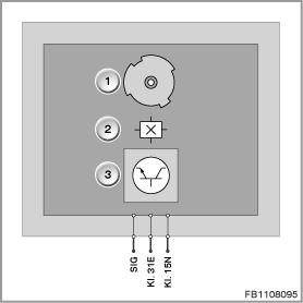
Index |
Explanation |
Index |
Explanation |
|---|---|---|---|
1 |
Camshaft sensor wheel |
2 |
Hall-effect sensor |
3 |
Electronic evaluation unit |
|
|
Pin assignments
Pin |
Explanation |
|---|---|
Kl. 15N |
Terminal 15N, power supply |
Kl. 31E |
Terminal 31, electronics ground |
SIG |
Signal line |
Signal path and target values
The engine control module reads in the sensor signal and compares the signal with a stored pattern.
The calibration between the sensor signal and stored pattern means that the exact position of the camshaft or the deviation is detected.
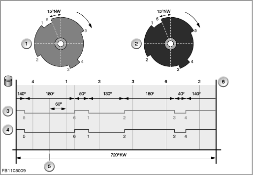
Index |
Explanation |
Index |
Explanation |
|---|---|---|---|
1 |
Intake camshaft |
2 |
Exhaust camshaft |
3 |
Intake camshaft signal |
4 |
Exhaust camshaft signal |
5 |
Reference mark for top dead centre, cylinder 1 (ignition) |
6 |
Cylinder |
Observe the following target values for the camshaft sensor:
Variable |
Value |
|---|---|
Voltage range |
6 to 16 Volts |
Engine speed range |
0 to |
Air gap range |
0.4 to 1.9 mm |
Maximum output current |
20 mA |
Temperature range |
-40 °C to 160 °C |
Diagnosis instructions
Failure of the component
If the camshaft sensor fails, the following behaviour is to be expected:
- Fault memory entry in the engine control module
- Emergency operation with substitute value
General information
The diagnosis for the camshaft sensor starts under the following conditions:
- DME main relay ON
- Engine running
- Engine is synchronized
- No stalling of the engine detected
- Error-free signal from the crankshaft sensor
No liability can be accepted for printing or other faults. Subject to changes of a technical nature