Coolant-temperature sensor
Coolant-temperature sensor
The coolant-temperature sensor is bolted in the housing of the coolant pump.
The coolant-temperature sensor converts the temperature of the coolant - and thus of the engine oil - into an electrical variable (resistance). To do so, a resistor with negative temperature coefficient (NTC) is used.
The coolant temperature is, among other things, the measured variable e.g. for the following calculations: injection quantity and nominal idle speed.
Functional description
A temperature-dependent electrical resistor is used for temperature detection. The circuit contains a power diplexer where the resistance can be measured depending on the temperature. This is converted into a temperature using a characteristic curve that is specific to the sensor.
A hot conductor (NTC) is installed in the coolant-temperature sensor; the resistance value of this hot conductor falls with rising temperature.
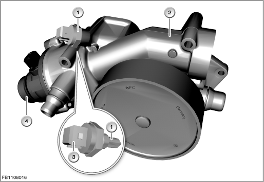
Index |
Explanation |
Index |
Explanation |
|---|---|---|---|
1 |
Coolant-temperature sensor |
2 |
Coolant pump |
3 |
Characteristic map thermostat |
4 |
2-pin plug-in connection |
The resistance changes depending on the temperature from 167 k to 150 , which corresponds to a temperature of -40 °C to 130 °C.
Structure and inner circuit
The coolant-temperature sensor is connected by means of a 2-pin plug-in connection.
The resistor is part of a voltage divider circuit that is supplied with 5 Volts by the engine management system.
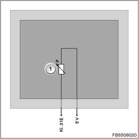
Index |
Explanation |
Index |
Explanation |
|---|---|---|---|
1 |
Hot conductor |
|
|
Pin assignments
Pin |
Explanation |
|---|---|
Kl. 31E |
Terminal 31, electronics ground |
5 V |
5 Volts, power supply |
Characteristic curve and target values
The electrical voltage at the resistor depends on the coolant temperature. A table that specifies the associated temperature for each voltage value is stored in the engine management system. This compensates for the non-linear relationship between electrical voltage and temperature.
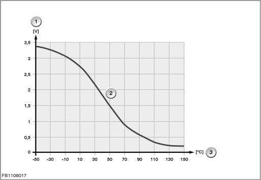
Index |
Explanation |
Index |
Explanation |
|---|---|---|---|
1 |
Voltage |
2 |
Characteristic curve for hot conductor (NTC) |
3 |
Temperature |
4 |
|
Observe the following target values for the coolant-temperature sensor:
Variable |
Value |
|---|---|
Nominal resistance at 25 °C |
2252 ± 1.5 % |
Current consumption |
1 mA |
Response time |
15 s |
Resolution of temperature |
± 1 °C |
Maximum output current |
20 mA |
Temperature range |
-40 °C to 150 °C |
Diagnosis instructions
Failure of the component
If the coolant-temperature sensor fails, the following behaviour is to be expected:
- Fault memory entry in the engine control module
- Emergency operation with substitute value
No liability can be accepted for printing or other faults. Subject to changes of a technical nature