Knock sensor
Knock sensor
The knock sensor are attached to the crankcase on the left and right.
The knock sensor detects the structure-borne sound vibrations (knock). Combustion knock can damage the engine. The data of the knock sensor enable the engine management system to counteract knocking. In the petrol engine, pinging combustion processes can occur under certain conditions. These pinging combustion processes reduce the earliest possible point of ignition and thus limit the power output and efficiency of the engine.
Functional description
These unwanted combustion processes are referred to as knocking (or pinging) and are the consequence of spontaneous combustions of mixture that has not yet encountered the flame front. Normal combustion and compression by the piston cause pressure and temperature increases that lead to spontaneous combustion of the mixture that is not yet burning. Here, flame speeds of more than 2000 m/s occur, whereas normal combustions involve flame speeds of around 30 m/s.
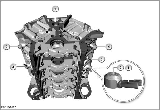
Index |
Explanation |
Index |
Explanation |
|---|---|---|---|
1 |
Crankcase |
2 |
Knock sensor for cylinders 1 and 2 |
3 |
Knock sensor for cylinders 3 and 4 |
4 |
Knock sensor for cylinders 5 and 6 |
5 |
Knock sensor for cylinders 7 and 8 |
6 |
2-pin plug-in connection |
Causes of knocking can be:
- Poor fuel quality (ROZ/MOZ)
- High cylinder charge
- High intake air and engine temperature
- Increased compression ratio (e.g. deposits)
If the knocking persists for a longer period, the pressure waves and thermal load can cause mechanical damage on the cylinder head gasket, on the piston and in the area of the valves. The characteristic vibrations of knocking combustions are picked up by the knock sensor, converted into electrical signals and sent to the engine management system. In the engine management system, the signals are processed in such a way that they can be assigned to the corresponding cylinder.
Structure and inner circuit
The signal is converted by a Piezo-ceramic disc. Pressure forces within the ceramic lead to a load shift that causes a voltage. This voltage is picked up by contact discs.
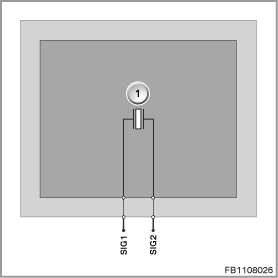
Index |
Explanation |
Index |
Explanation |
|---|---|---|---|
1 |
Knock sensor |
|
|
Pin assignments
Pin |
Explanation |
|---|---|
SIG1 |
Differential signal 1 |
SIG2 |
Differential signal 2 |
Characteristic curve and target values
The knock sensor shows linear characteristics in the frequency range up to around 20 kHz. The resonance frequency of the sensor itself lies at a significantly higher frequency (greater than 30 kHz). The knocking sounds that usually occur in the engine have frequencies of around 7 kHz.
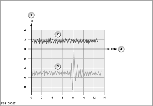
Index |
Explanation |
Index |
Explanation |
|---|---|---|---|
1 |
Voltage |
2 |
Signal without knocking |
3 |
Signal with knocking |
4 |
Frequency |
Observe the following target values for the crankshaft sensor:
Variable |
Value |
|---|---|
Voltage range |
4.5 to 5.5 Volts |
Frequency range |
7 to 25 kHz |
Maximum output current |
20 mA |
Outside temperature |
-40 °C to 140 °C |
Diagnosis instructions
Failure of the component
If the crankshaft sensor fails, the following behaviour is to be expected:
- Fault memory entry in the engine control module
- Emergency operation with substitute value (retarding of the ignition)
No liability can be accepted for printing or other faults. Subject to changes of a technical nature