Characteristic map thermostat
Characteristic map thermostat
The characteristic map thermostat is attached to the housing of the coolant pump.
The coolant temperature influences:
- Fuel consumption
- Power output
- Quality of the mixture formation
- Pollutant emissions
- Mechanical load on components
Optimization of these variables does not permit a fixed temperature with the different engine speed and load states. Optimization requires a temperature range that corresponds to each operating point.
The characteristic map thermostat enables convergence towards the optimal temperature.
Functional description
Input variables for calculation by the engine management system are:
- Engine speed
- Load
- Road speed
- Intake air temperature
- Coolant temperature
The engine management system uses the above input variables to calculate the optimal coolant temperature for each operating point. The optimal coolant temperature is influenced by specific heating of the wax element in the characteristic map thermostat as well as activation of the electric fan according to requirements. At full load, lower coolant temperatures improve the cylinder filling. Moreover, lower engine temperatures reduce the risk of knocking. The power output and torque can thus be positively influenced.
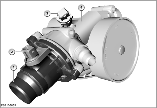
Index |
Explanation |
Index |
Explanation |
|---|---|---|---|
1 |
Characteristic map thermostat |
2 |
2-pin plug-in connection |
3 |
Coolant-temperature sensor |
4 |
Coolant pump |
A heater resistor is located in the wax element of the characteristic map thermostat. The engine management system supplies the heater resistor with current. This expands the wax element and closes the inlet of the cylinder head using spring pressure. The spring has the task of pushing the characteristic map thermostat back into the rest position when the wax element cools down.
The cooling circuit with a cold engine passes via the inlet of the cylinder head via the characteristic map thermostat to the return line to the coolant pump.
Structure and inner circuit
The characteristic map thermostat is connected by means of a 2-pin plug-in connection.
The characteristic map thermostat is supplied with 12 Volts vehicle voltage by the engine management system. Activation by the engine management system is on the ground side.
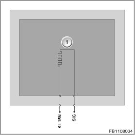
Index |
Explanation |
Index |
Explanation |
|---|---|---|---|
1 |
Heater resistor in the characteristic map thermostat |
|
|
Pin assignments
Pin |
Explanation |
|---|---|
Kl. 15N |
12 Volts, power supply |
SIG |
Activation of heater resistor |
Temperature characteristics and target values
The engine management system activates the heating element via a characteristic map depending on the current driving situation.
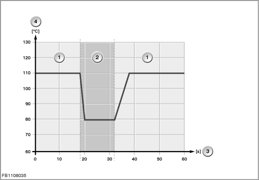
Index |
Explanation |
Index |
Explanation |
|---|---|---|---|
1 |
Heater resistor not activated |
2 |
Heater resistor activated |
3 |
Time |
4 |
Coolant temperature |
Observe the following target values for the coolant-temperature sensor:
Variable |
Value |
|---|---|
Voltage range |
9 to 16 Volts |
Opening temperature, unheated |
97 °C |
Minimum stroke |
8 mm |
Minimum stroke in the control range |
4.5 mm |
Maximum output current |
20 mA |
Temperature range |
-40 °C to 150 °C |
Diagnosis instructions
Failure of the component
If the characteristic map thermostat fails, the following behaviour is to be expected:
- Fault memory entry in the engine control module
- Conventional operation via wax element
- US version: The emissions warning lamp lights up in the instrument cluster
No liability can be accepted for printing or other faults. Subject to changes of a technical nature