Intake air temperature-intake manifold pressure sensor
Intake air temperature-intake manifold pressure sensor
The intake-air temperature / intake-manifold pressure sensor is bolted onto the intake air collector.
This combined sensor delivers the following information to the engine management system:
- Temperature after the throttle valve
- Air intake pressure after the throttle valve
The intake-air temperature / intake-manifold pressure sensor is used to calculate the intake air flow rate. The pressure also serves as a substitute value for the load signal.
Functional description
Intake pipe pressure sensor
Expansion measurement strips are used to detect the pressure.
The pressure applied deforms a steel membrane in the sensor that is fitted with expansion measurement strips. The changes in resistance in the expansion measurement strips are detected electronically by a measurement bridge and evaluated. The measured voltage is then included as an actual value in the charge-air pressure control.
Intake air temperature sensor
A temperature-dependent electrical resistor is used for temperature detection. The circuit contains a power diplexer where the resistance can be measured depending on the temperature. This is converted into a temperature using a characteristic curve that is specific to the sensor.
A hot conductor (NTC) is installed in the intake air temperature sensor; the resistance value of this hot conductor falls with rising temperature. The resistance changes depending on the temperature from 167 k to 150 , which corresponds to a temperature of -40 °C to 130 °C.
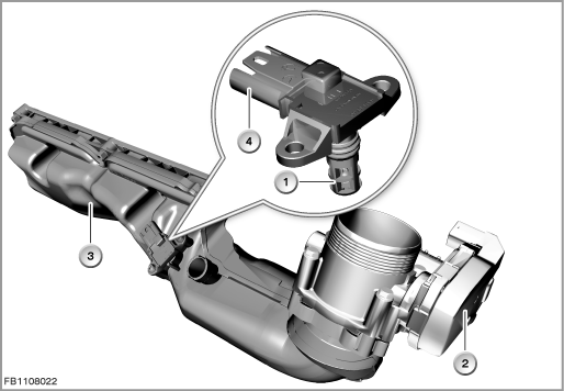
Index |
Explanation |
Index |
Explanation |
|---|---|---|---|
1 |
Intake air temperature-intake manifold pressure sensor |
2 |
Throttle-valve actuator |
3 |
Intake air collector |
4 |
4-pin plug-in connection |
Structure and inner circuit
The intake-air temperature / intake-manifold pressure sensor is connected by means of a 4-pin plug-in connection.
The sensor is supplied with 5 Volts by the engine management system.
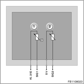
Index |
Explanation |
Index |
Explanation |
|---|---|---|---|
1 |
Intake-manifold pressure sensor |
2 |
Intake air temperature sensor |
Pin assignments
Pin |
Explanation |
|---|---|
Kl. 31E |
Terminal 31, electronics ground |
SIG1 |
Air intake pressure signal |
5 V |
5 Volts, power supply |
SIG2 |
Intake-air temperature signal |
Characteristic curve and target values
The air intake pressure information is sent to the engine management system across a signal line.
The signal for the air intake pressure, which can be evaluated, fluctuates depending on the pressure. The measuring range of approx. 0.5 to 4.5 Volts corresponds to an air intake pressure of 15 kPa (0.15 bar) to 120 kPa (1.2 bar).
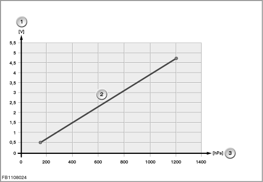
Index |
Explanation |
Index |
Explanation |
|---|---|---|---|
1 |
Voltage |
2 |
Characteristic curve for hot conductor (NTC) |
3 |
Temperature |
4 |
|
The resistance of the intake air temperature sensor changes depending on the temperature from 167 k to . This corresponds to a temperature of -40 °C to 130 °C.
Observe the following target values for the intake-manifold pressure sensor:
Variable |
Value |
|---|---|
Voltage range of intake-manifold pressure sensor |
0.5 to 4.5 Volts |
Measuring range of air intake pressure |
0.15 to 1.2 bar |
Resolution of intake-air temperature |
± 1 °C |
Maximum output current |
10 mA |
Temperature range |
-40 °C to 130 °C |
Diagnosis instructions
Failure of the component
If the intake-air temperature / intake-manifold pressure sensor fails, the following behaviour is to be expected:
- Fault memory entry in the engine control module
- Emergency operation with substitute value
No liability can be accepted for printing or other faults. Subject to changes of a technical nature