Refrigerant pressure sensor
Refrigerant pressure sensor
The refrigerant pressure sensor for the air conditioning system is installed in the high pressure line between the condenser and evaporator.
In the cooling mode, the refrigerant pressure is detected by the refrigerant pressure sensor and evaluated in the IHKA control module (”IHKA” stands for ”integrated automatic heating and air conditioning system”).
Depending on the sensor signal, the output of the A/C compressor is reduced or switched off by the IHKA control module in the event of excessively high refrigerant pressure.
Depending on the refrigerant pressure, a fan setting is determined via the IHKA control module and forwarded on the bus to the engine control module.
Functional description
The refrigerant pressure sensor uses a pressure-sensitive element to evaluate the refrigerant pressure present in the high pressure line of the refrigerant circuit.
The refrigerant pressure sensor is supplied with constant voltage. The actual measured signal is a linear output voltage of the sensor dependent on the refrigerant pressure. This output voltage is evaluated by the junction box electronics (JBE) and converted into a pressure signal. The pressure signal is then converted into a digital signal and sent on the bus to the IHKA control module.
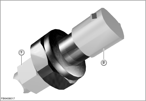
Index |
Explanation |
Index |
Explanation |
|---|---|---|---|
1 |
Refrigerant pressure sensor |
2 |
3-pin plug-in connection |
Structure and inner circuit
The junction box electronics (JBE) supply the refrigerant pressure sensor with 5 Volts and ground.
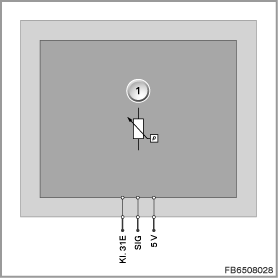
Index |
Explanation |
Index |
Explanation |
|---|---|---|---|
1 |
Pressure sensor |
|
|
Pin assignments
Pin |
Explanation |
|---|---|
Kl. 31E |
Terminal 31, electronics ground |
SIG |
Signal line |
5 V |
5 Volts, power supply |
Characteristic curve and target values
The signal from the refrigerant pressure sensor fluctuates depending in the pressure. The measuring range of approx. 0.4 to 4.6 Volts corresponds to a pressure of approx. 10 kPa (0.1 bar) to 3.5 kPa (35 bar).
The fan setting in each case is only dependent on the refrigerant pressure.
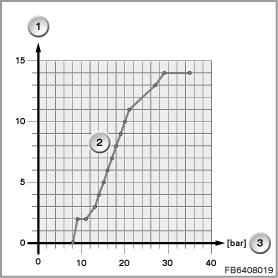
Index |
Explanation |
Index |
Explanation |
|---|---|---|---|
1 |
Fan stage |
2 |
Characteristic curve for refrigerant pressure sensor |
3 |
Refrigerant pressure in bar |
|
|
Observe the following target values for the outdoor temperature sensor:
Variable |
Value |
|---|---|
Voltage range |
4.5 to 5.5 V |
Current consumption |
Less than 20 mA |
Temperature range |
-40 to 85 °C |
Diagnosis instructions
Failure of the component:
If the refrigerant pressure sensor fails, the following behaviour is to be expected:
- Fault memory entry in the IHKA control module
- The A/C compressor is switched off or is not switched on.
No liability can be accepted for printing or other faults. Subject to changes of a technical nature