Accelerator pedal module
Accelerator pedal module
The accelerator pedal module detects the accelerator pedal position and thus sends the driver's demand in the form of an electrical signal to the engine management system.
Functional description
The accelerator pedal position is picked up by 2 sensors separately. Two 2 sensors are used to enable redundancy, monitoring and fault detection.
The accelerator pedal travel is detected by the sensors as an angle and output directly to the engine management system as an analogue, linear voltage characteristic curve via the pedal angle (°). The total mechanically feasible accelerator pedal travel is 16° ± 0.5°.
Each change to the accelerator pedal position is sent to the engine management system within a maximum of 50 milliseconds. The sensor signals are transferred as analogue.
The engine management system monitors the two input signals of the sensors and compares them for plausibility (e.g. synchronization, linearity).
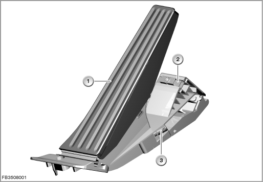
Index |
Explanation |
Index |
Explanation |
|---|---|---|---|
1 |
Accelerator pedal |
2 |
Full-load stop |
3 |
6-pin plug-in connection |
|
|
The accelerator pedal is returned on closure of the throttle by means of spring elements.
Structure and inner circuit
The accelerator pedal module works according to the inductive principle.
The two sensors are supplied separately with 5 Volts and ground by the engine control module.
Depending on the accelerator pedal position, the electronic evaluation unit generates analogue voltage signals for the engine management system. The sensor signals are transferred separately to the engine control module.
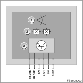
Index |
Explanation |
Index |
Explanation |
|---|---|---|---|
1 |
Accelerator pedal position |
2 |
Hall sensors |
3 |
Electronic evaluation unit |
|
|
Pin assignments
Pin |
Explanation |
|---|---|
Kl. 31E |
Terminal 31, electronics ground, sensor 1 |
Kl. 31E |
Terminal 31, electronics ground, sensor 2 |
5 V |
Power supply 5 Volts, sensor 2 |
SIG1 |
Signal line, sensor 1 |
5 V |
Power supply 5 Volts, sensor 1 |
SIG 2 |
Signal line, sensor 2 |
Characteristic curve and target values
The characteristic curve shows an accelerator pedal module with kick-down switch.
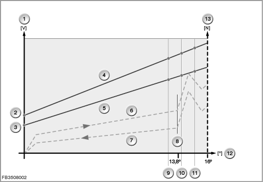
Index |
Explanation |
Index |
Explanation |
|---|---|---|---|
1 |
Sensor voltage in Volts (V) |
2 |
Sensor voltage at idle speed, sensor 1 |
3 |
Sensor voltage at idle speed, sensor 2 |
4 |
Course of output signal, sensor 1 |
5 |
Course of output signal, sensor 2 |
6 |
Characteristic curve for rising pedal force |
7 |
Characteristic curve for falling pedal force (closure of the throttle) |
8 |
Increase in pedal force due to start of kick-down or drop in pedal force due to end of kick-down |
9 |
Full-load position without kick-down |
10 |
Kick-down OFF |
11 |
Kick-down ON |
12 |
Pedal angle in degrees (°) |
13 |
Pedal force in Newtons (N) |
|
|
Start of kick-down:
The application point for the increased pedal force is at 13.8° at the earliest and at 1.6° at the latest before the mechanical end stop.
On the characteristic curve for rising pedal force, the threshold value for kick-down ON must lie immediately after the maximum pedal force for start of kick-down.
End of kick-down:
The end point for the increased pedal force is 1.6° at the earliest before the mechanical end stop and at 13.8° at the latest.
On the characteristic curve for falling pedal force, the threshold value for kick-down OFF must lie immediately after the maximum pedal force.
Voltage values:
The signal value of the two sensors are percentages related to the power supply.
Sensor 1: At idle speed, the value is 15 % of the power supply; at the end stop approx. 90 %.
Sensor 2: At idle speed, the value is 7.5 % of the power supply; at the end stop approx. 45 %.
Observe the following target values for the accelerator pedal module:
Variable |
Value |
|---|---|
Voltage range |
4.5 to 5.5 V |
Maximum current consumption |
15 mA |
Temperature range |
-40 to 80 °C |
Diagnosis instructions
Failure of the component:
The accelerator pedal module merely provides the driver's demand. This means the accelerator pedal module does not intervene directly in other actuators. The engine management system must ensure that the vehicle assumes a safe state if the sensor signals fail.
If the component fails, the following behaviour is to be expected:
- Failure of a sensor signal
- Fault memory entry in the engine control module
- Check Control message
- Emergency engine program (drive of the vehicle electronically limited, journey may continue conditionally)
- Fault memory entry in the engine control module
- Failure of both sensor signals
- Fault memory entry in the engine control module
- Check Control message
- Emergency engine program (no longer possible to continue driving, engine in idle operation)
- Fault memory entry in the engine control module
No liability can be accepted for printing or other faults. Subject to changes of a technical nature