Ionizer
Ionizer
The ionizer is installed on the heater/air conditioner.
The ionizer treats the air upstream of the evaporator. The treatment prevents bacterial growth, thus preventing smells in the vehicle interior.
The ionizer is connected to the integrated automatic heating / air-conditioning system (IHKA).
Each automatic heating / air-conditioning system (e.g. 2.5-zone and 4-zone) has the ionizer as series standard.
Functional description
There is a ceramic plate in the ionizer. The application of a device-internal high voltage leads to partial ionization of the air. The reaction generates hydrogen peroxide. The hydrogen peroxide produces a chemical reaction that removes bacteria for the most part from the evaporator and other components of the automatic air-conditioning system.
Applying AC voltage splits oxygen molecules in a multi-stage reaction into single-atom oxygen. After a few milliseconds, this single-atom oxygen combines to form triple-atom oxygen O3. Part of the O3 generated reacts with the condensate on the evaporator. Oxidation destroys bacteria and germs.
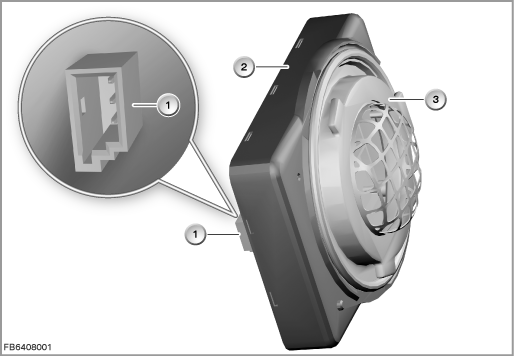
Index |
Explanation |
Index |
Explanation |
|---|---|---|---|
1 |
3-pin plug-in connection |
2 |
Housing |
3 |
Ionizer |
|
|
The ionizer is controlled depending on the automatic program as well as the operating state of the vehicle.
The IHKA sends a pulse-width modulated signal to activate the ionizer.
Structure and inner circuit
The ceramic plate is covered with toughened glass. Electrical conductors are attached to the front and back. An AC voltage of approx. 3 kV is applied to the electrode by the control electronics circuit.
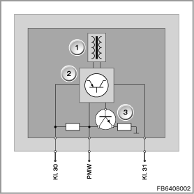
Index |
Explanation |
Index |
Explanation |
|---|---|---|---|
1 |
Electrodes |
2 |
Control electronics |
3 |
Transistor |
|
|
Pin assignments
Pin |
Explanation |
|---|---|
Terminal 30 |
Terminal 30, power supply |
PWM |
Pulse-width modulated signal (clocked) |
Terminal 31 |
Terminal 31, ground |
Target values and signal path
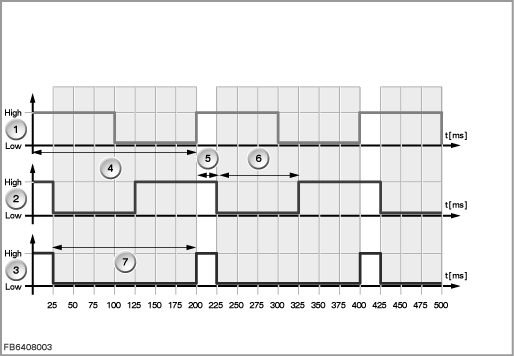
The ionizer distinguishes between reversible faults (caused by outside influences) and irreversible faults. Both fault classes are detected.
The information signal is sent on the bidirectional line (PWM).
Example of signal path with irreversible fault:
Index |
Explanation |
Index |
Explanation |
|---|---|---|---|
1 |
Automatic climate control (IHKA) |
2 |
Ionizer |
3 |
Resulting signal |
4 |
Clock pulse for control operation 200 ms |
5 |
Waiting period of 25 ms after rising edge of IHKA |
6 |
Signal Low for 100 ms |
7 |
IHKA detects signal Low for 175 ms |
|
|
Observe the following target values for the ionizer:
Variable |
Value |
|---|---|
Power supply |
13.5 V |
Overvoltage |
max. 16.5 V |
Undervoltage |
min. 10 V |
Maximum constant current consumption |
830 mA |
Outside temperature |
-40 to 80 °C |
Relative atmospheric humidity |
10 to 100 % |
Diagnosis instructions
Failure of the component
If the ionizer fails, the following behaviour is to be expected:
- Fault memory entry in the IHKA
- No activation of the ionizer
No liability can be accepted for printing or other faults. Subject to changes of a technical nature