Alternator
Alternator
The alternator exchanges data with the engine control module using a bit-serial data interface. The alternator provides the engine control module with information, e.g. type and manufacturer. This enables the engine control module to adapt control of the alternator to the alternator model fitted.
Functional description
The alternator maintains the desired level of vehicle voltage. The alternator also supplies all electrical consumer units during vehicle operation. The regulator regulates the output voltage of the electrically excited alternator with uncontrolled rectifier by applying the excitation current.
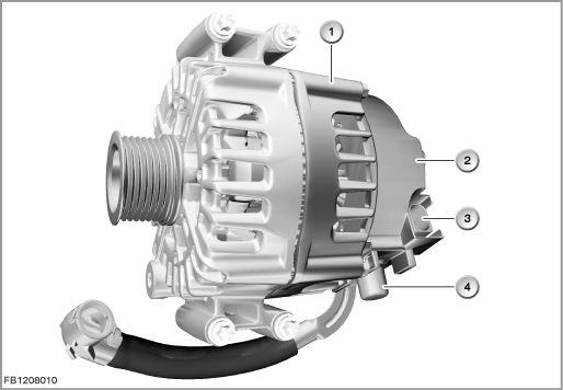
Example
Index |
Explanation |
Index |
Explanation |
|---|---|---|---|
1 |
Alternator |
2 |
Regulator |
3 |
2-pin plug-in connection (1 pin used) |
4 |
Positive battery lead |
For the alternator with bit-serial data interface, the following functions are implemented in the engine control module:
- Switching the alternator on and off on the basis of defined parameters
- Specification of the maximum permitted power consumption of the alternator
- Calculation of the input torque for the alternator from the power consumption
- Control of the reaction of the alternator with addition of high power consumers (load-response function)
- Diagnosis of the data line between alternator and engine control module
- Storage of any faults that occur on the alternator in the fault memory of the engine control module
- Activation of the charge control lamp in the instrument cluster via bus connection
Structure and inner circuit
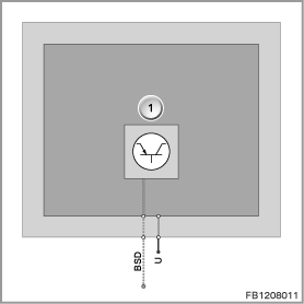
The alternator has a separate terminal for the positive battery lead. The control variables (e.g. target voltage of alternator) are transferred to the regulator across the bit-serial data interface (BSD).
The regulator is attached to the back of the alternator.
Index |
Explanation |
Index |
Explanation |
|---|---|---|---|
1 |
Electronic module with regulator |
|
|
Pin assignments
Pin |
Explanation |
|---|---|
BSD |
Bit-serial data interface |
U |
Positive battery lead |
Characteristic curve and target values
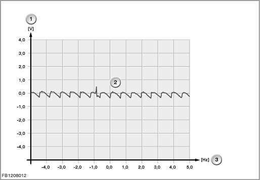
The oscilloscope represents the voltage progression of an intact alternator. The level of the individual waves depends on the current load of the alternator. The length of the waves depends on the engine speed. The higher the engine speed the shorter the waves. At idle speed with consumer units switched on, a fault-free alternator must deliver the following characteristic curve:
Index |
Explanation |
Index |
Explanation |
|---|---|---|---|
1 |
Voltage |
2 |
Characteristic curve |
3 |
Frequency |
|
|
Observe the following target values for the alternator:
Variable |
Value |
|---|---|
Voltage range |
6 to 16 V |
Data frequency on bit-serial data interface |
1164 to 1236 bit/s |
Maximum temperature of the stator winding |
260 °C |
Maximum speed |
20000 rpm |
Temperature range of regulator |
-40 to 140 °C |
Diagnosis instructions
Failure of the component
The main function of the alternator is also ensured in the event of interruption of the communication between the alternator and the engine control module. The following fault causes are distinguishable by the fault memory entries:
- Overheating protection:
the alternator is overloaded. For safety reasons, the alternator voltage is reduced until the alternator has cooled down again (the charge control lamp does not light up). - Mechanical fault:
There is a mechanical block in the alternator. Or the belt drive is defective. - Electrical fault: Excitation diode defective, excitation coil has been interrupted, overvoltage due to defective regulator.
- Communication failure: Defective cable between engine control module and alternator.
An interrupt or short circuit in the coils of the alternator cannot be detected.
No liability can be accepted for printing or other faults. Subject to changes of a technical nature