Fans in driver or passenger backrest
Fans in driver or passenger backrest
The active seat ventilation enables individual cooling of the seat cushion and backrest.
Nine fans are installed in the driver's and passenger's seat.
The fans are distributed as follows:
- 5 fans in the seat cushion (referred to as fan seat cushion), of which one fan is in the thigh support (housing made of cast aluminium)
- 4 fans in the backrest (housing made of plastic)
The fans in the seat cushion and in the backrest are switched in parallel.
The fan in the thigh support is not connected to the power supply for the fans in the seat cushion. For acoustic reasons, the fan is connected to the power supply for the fans in the backrest.
Background: After an operating period of 10 minutes, the system switches the fan in the backrest automatically from ventilation stage 3 to ventilation stage 2.
Functional description
The active seat ventilation can be switched on as of Terminal 15 ON using the button for active seat assignment.
The first time the button for active seat ventilation is pressed, the driver seat module (SMFA) or passenger seat module (SMBF) activates the fans. Ventilation stage 3 (high speed stage) is switched on. Further button pressures switch on the next-lowest ventilation stage 2 (low ventilation stage) or switch off the active seat ventilation.
The specified speed stage from the seat module as well as output of an alarm status of a fan motor if it comes to a standstill takes place across the control and diagnosis lead.
To change over to the lower speed stage, the transistor in the seat module becomes conductive.
If a fan motor is not rotating (alarm status), the transistor also switches a resistance against terminal 31. Evaluation of this diagnosis feedback is only possible if the interface for the fans is switched to ventilation stage 3 (high speed stage).
The seat module detects undervoltage and overvoltage and switches off the fans in the backrest.
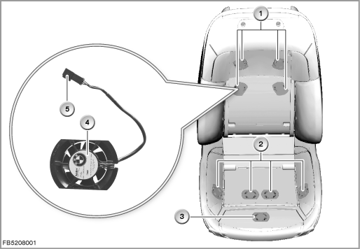
Index |
Explanation |
Index |
Explanation |
|---|---|---|---|
1 |
Fans in the backrest |
2 |
Fans in the seat cushion |
3 |
Fan in the thigh support |
4 |
Fan |
5 |
3-pin plug-in connection |
|
|
Structure and inner circuit
The fans in the backrest are switched in parallel and are supplied with voltage by the seat module. The ventilation stages are switched via the transistor in the seat module.
Each fan has a control / diagnosis lead in addition to the power supply and earth connection. The speed stages of the fans are activated and the fans are monitored via this control and diagnosis lead.
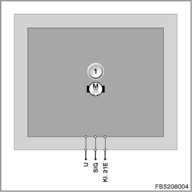
Index |
Explanation |
Index |
Explanation |
|---|---|---|---|
1 |
Fan |
|
|
Pin assignments
Pin |
Explanation |
|---|---|
Terminal 31E |
Terminal 31, electronics ground |
U |
Power supply from seat module |
SIG |
Control and diagnosis lead |
Target values
The static pressure lies between 10.5 Pa (low speed stage) and 22.5 Pa (high speed stage).
Observe the following target values for the fans in the backrest:
Variable |
Value |
|---|---|
Voltage range |
9 to 16 V |
Maximum speed, high speed stage |
3600 rpm |
Maximum speed, low speed stage |
2450 rpm |
Maximum output, high speed stage |
1.56 W |
Maximum output, low speed stage |
1.11 W |
Maximum current consumption, high speed stage |
0.12 A |
Maximum current consumption, low speed stage |
0.08 A |
Temperature range |
-30 to 80 °C |
Diagnosis instructions
Failure of the component
If a fan in the backrest fails due to a short circuit or break in wiring, the following behaviour is to be expected:
- Fault memory entry in the driver seat module (SMFA) or passenger seat module (SMBF)
- All the fans in the backrest as well as the fan in the thigh support are inoperative
With the fault ”at least one fan in alarm status” (fan at standstill despite activation), the following behaviour is to be expected:
- Fault memory entry in the driver seat module (SMFA) or passenger seat module (SMBF)
- As of failure of 2 fans, the lower ventilation stage is activated.
General information
The energy management in the vehicle can briefly switch off the active seat ventilation depending on the energy balance. The function indicator, however, remains active.
No liability can be accepted for printing or other faults. Subject to changes of a technical nature