Backrest fan for the driver's and/or passenger's side, rear
Backrest fan for the driver's and/or passenger's side, rear
The active seat ventilation in the rear enables individual cooling of the seat cushion and rear seat back.
Four fans are installed in the rear seats, two on the driver's side, rear and two on the passenger's side, rear:
- 1 fan for ventilation of the seat cushion
(seat cushion fan for the driver's and/or passenger's side, rear) - 1 fan for ventilation of the rear seat back
(fan for the backrest on the driver's and/or passenger's side, rear)
Functional description
The seat cushion fan for the driver's and/or passenger's side, rear draws in air from the rear footwell.
The fan is connected to a climate pad. The air that is drawn in is fed to the backrest via the climate pad. The climate pad has openings in the area of the backrest. The air drawn in by the fan flows through these openings, thus cooling the cushion cover.
The rear active seat ventilation can be switched on as of terminal 15 ON using the button for rear active seat assignment.
The speed stage of the seat module for the driver's and/or passenger's side, rear as well as issue of an alarm status from the fan motor at a standstill are set via the control and diagnosis lead.
To switch over to the lower speed stage, the transistor in the seat module becomes conductive.
If the fan motor is not rotating (alarm status), the transistor also switches a resistance against terminal 31. Evaluation of this diagnosis feedback is only possible if the interface for the fans is switched to ventilation stage 3 (high speed stage).
The seat module detects undervoltage and overvoltage and switches off the backrest fan on the driver's and/or passenger's side.
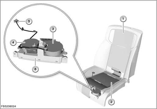
Index |
Explanation |
Index |
Explanation |
|---|---|---|---|
1 |
Climate pad in the backrest on the driver's and/or passenger's side, rear |
2 |
Climate pad in the seat cushion on the driver's and/or passenger's side, rear |
3 |
Backrest fan for the driver's and/or passenger's side, rear |
4 |
Seat cushion fan for the driver's and/or passenger's side, rear |
5 |
Plug-in connection |
6 |
Mounting for the fans |
Structure and inner circuit
The backrest fan on the driver's and/or passenger's side is supplied with voltage by the seat module. The fan stages are switched via the transistor in the seat module.
Each fan has a control / diagnosis lead in addition to the power supply and earth connection. The speed stages of the fan are activated via this control and diagnosis lead. The fans are also monitored via the control and diagnosis lead.
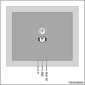
Index |
Explanation |
Index |
Explanation |
|---|---|---|---|
1 |
Fan |
|
|
Pin assignments
Pin |
Explanation |
|---|---|
Terminal 31E |
Terminal 31, electronics ground |
U |
Power supply from seat module |
SIG |
Control and diagnosis lead |
Target values
The static pressure is a maximum of 284 Pa (high speed stage).
Comply with the following target values for the backrest fan for the driver's and/or passenger's side, rear:
Variable |
Value |
|---|---|
Voltage range |
9 to 16 V |
Maximum output, high speed stage |
7.97 W |
Maximum output, low speed stage |
2.57 W |
Maximum current consumption, high speed stage |
0.59 A |
Maximum current consumption, low speed stage |
0.19 A |
Temperature range |
-40 to 85 °C |
Diagnosis instructions
Failure of the component
If the backrest fan for the driver's and/or passenger's side, rear fails due to a short circuit or break in wiring, the following behaviour is to be expected:
- Fault memory entry in the seat module for the driver's side, rear (SMFAH) and/or seat module for the passenger's side, rear (SMBFH)
With the fault ”Fan in alarm status” (fan at standstill despite activation), the following behaviour is to be expected:
- Fault memory entry in the seat module for the driver's side, rear (SMFAH) and/or seat module for the passenger's side, rear (SMBFH)
General information
The energy management in the vehicle can briefly switch off the rear active seat ventilation depending on the energy balance. The function indicator, however, remains active.
No liability can be accepted for printing or other faults. Subject to changes of a technical nature