Footwell flap motor, front left
Footwell flap motor, front left
The footwell-flap motor is the drive for the front left footwell flap. The footwell flap is used to regulate the ventilation of the vehicle interior in the front left footwell (IHKA High).
In the IHKA Basis (base version of the integrated automatic heating and air conditioning system), the footwell flap regulates the ventilation for the front left footwell and on the left-hand side of the rear.
The drive consists essentially of the following parts:
- Front left footwell-flap motor (actuator drive)
- Electronic module (with integrated circuit)
- Transmission
- Housing
Functional description
The footwell-flap motor is activated and supplied with voltage and ground across the LIN bus by the control module of the integrated automatic heating / air-conditioning system (IHKA control module).
In the idle state, the IHKA control module switches the power supply off.
The footwell-flap motor is fitted with an integrated circuit. This circuit controls the coil of the footwell-flap motor. The circuit is bus- and diagnosis-compatible.
After activation of the footwell-flap motor, the integrated circuit sends a position message (actual position) to the IHKA control module.
After the vehicle is stopped and parked and after a specified waiting period (stored in the memory chip of the IHKA control module), the footwell-flap motor is moved to a certain parking position. The footwell-flap motor is re-initialized to this parking position after starting up.
- Shutdown in the event of blocking
The integrated circuit detects blocking of the footwell-flap motor in that there is increased current consumption within the adjustment range. The integrated circuit reports the fault across the LIN bus to the IHKA control module. The IHKA control module no longer activates the defective footwell-flap motor.
If the blocking occurs outside of the adjustment range, an end stop is detected correctly. - Reference run
The footwell-flap motor is unable to detect the current position (actual position). The footwell-flap motor always moves relative to an end position of the footwell flap (reference point). One of the end positions of the footwell flap (closed or fully opened) serves as the reference point.
The footwell flap is moved to an end position as follows:- if the IHKA control module is exchanged, or
- if the power supply is interrupted.
The reference run can also be initiated by the BMW diagnosis system. - if the IHKA control module is exchanged, or
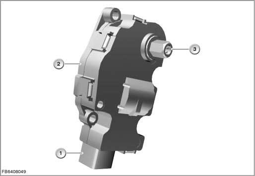
Index |
Explanation |
Index |
Explanation |
|---|---|---|---|
1 |
4-pin plug-in connection |
2 |
Footwell-flap motor |
3 |
Gearbox output |
|
|
Structure and inner circuit
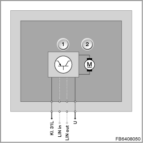
The footwell-flap motor is connected to the IHKA control module by means of a 4-pin plug-in connection.
Index |
Explanation |
Index |
Explanation |
|---|---|---|---|
1 |
Electronic module |
2 |
Footwell-flap motor |
Pin assignments
Pin |
Explanation |
|---|---|
Terminal 31L |
Terminal 31, load ground |
LIN in |
LIN bus input |
LIN out |
LIN bus output |
U |
Power supply |
Target values
Observe the following target values for the front left footwell-flap motor:
Variable |
Value |
|---|---|
Power supply |
12 V |
Voltage range |
8 to 16 V |
Temperature range |
-40 ± 85 °C |
Diagnosis instructions
The flap motors communicate across the LIN bus with the IHKA control module. The flap motors are switched in series on the LIN bus.
The flap motors in the IHKA (integrated automatic heating and air conditioning system) are all the same. During operation, the only difference between them is their programmed address.
Each flap motor is assigned a certain address. The address determines what function the flap motor assumes in the composite system. This address tells e.g. the front left footwell-flap motor that messages are being addressed to it (e.g. 'open flap'). This address also tells e.g. the IHKA control module which flap motor has sent it a fault message.
A precondition for successful addressing of the flap motors is correct coding of the IHKA control module (e.g. IHKA with or without rear automatic climate control).
After starting the auto-addressing, an address is programmed into the flap motor that is topologically last in the series connection. Then an address is programmed into the topologically second-last flap motor etc. until all the addresses have been assigned. This means that the installation location of the flap motor in the wiring harness decides which address is programmed into the flap motor.
If e.g. during auto-addressing the topologically last flap motor is not connected to the wiring harness of the IHKA control module or there is no connection via the LIN bus, the topologically second-last flap motor is erroneously detected as the topologically last flap motor. This means that the wrong address is written into this flap motor. The remaining stepper motors are also given an incorrect address.
Confusing connectors also leads to incorrect addressing.
If a number of flap motors are entered in the fault memory with the fault ”not responding”, there is probably a break in the connection via the LIN bus.
The search for the break (cable, connector, flap motor) must then start at the topologically first of the entered flap motors.
Failure of the component:
If the front left footwell-flap motor fails, the following behaviour is to be expected:
- Fault memory entry in the IHKA control module
- Emergency operation: If a fault occurs, e.g. no bus communication over a certain period of time, emergency operation starts.
During emergency operation, the footwell-flap motor is no longer activated. This means that the front left footwell flap remains in its current position.
No liability can be accepted for printing or other faults. Subject to changes of a technical nature